



Contents: Removal ↓ Installation ↓
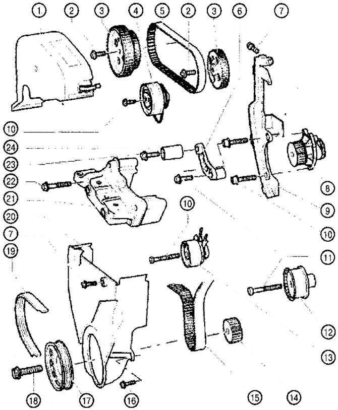
VC 1.064. Timing drive for 1.4 l VSA and BUD petrol engines:
1. Upper part of the toothed belt guard
2. Camshaft pulley mounting screw
- Tightening: 20 Nm + 90°
- Replace with a new one
- Use a camshaft locking tool to loosen and tighten
3. Timing pulley of the camshaft
- Maintain the correct position when installing the timing belt
4. Tension roller of the mating belt drive
5. Toothed belt of the coupled drive
- Before removing, mark the direction of travel
- Check for wear
- Avoid fractures
6. Bracket (only available in the VSA engine)
- Fastening tightening: 7-10 Nm
8. Coolant pump
- If damaged, replace the entire assembly
9. Rear timing belt guard
10. Screw: 20 Nm
11. Screw: 50 Nm
12. Fixed roller of the main drive toothed belt
13. Main drive belt tension roller
14. Crankshaft toothed pulley
15. Main drive toothed belt
- Before removing, mark the direction of travel
- Check for wear
- Avoid fractures
15. Screw: 12 Nm
- Replace with a new one
17. Crankshaft pulley (poly V-belt)
18. Crankshaft pulley mounting screw
19. Poly V-belt
- Before removing, mark the direction of the belt with chalk or a felt-tip pen
- Check for wear
- Avoid fractures
20. Lower part of the toothed belt protective cover
21. Engine bracket
22. Screw: 50 Nm
- Replace with a new one
23. Screw: 25 Nm (only available in the VSA engine)
24. Idler pulley (only available in the VSA engine)
Removal
Engine with the letter designation BSA
1. Remove the air filter housing.
Engine with the letter designation BUD
1. Remove the air filter housing.
Continuation of the description of works for all vehicles
2. Remove the top part of the timing belt cover.
3. Remove the soundproofing casing.
4. Remove the front right fender liner.
5. Mark the direction of rotation of the poly V-belt and remove the belt.
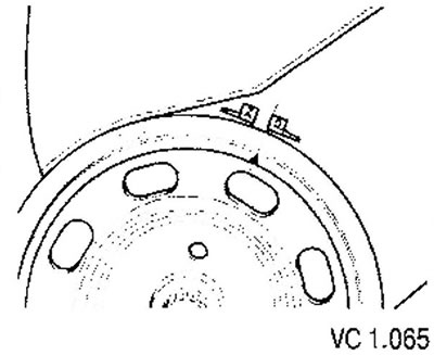
6. Set the crankshaft to TDC of the 1st cylinder. The notch on the poly V-belt pulley must align with the edge of the mark (O).
The fixing holes in the camshaft sprockets must align with the holes in the camshaft housing (arrows).
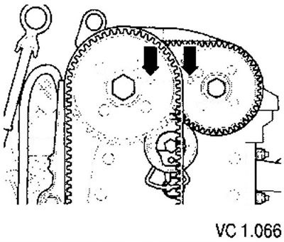
If the fixing holes are on opposite sides of the sprockets, the crankshaft must be turned one more revolution.
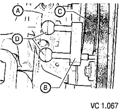
7. Secure both camshaft sprockets with a locking tool (see figure VC1.067) as follows.
- Insert both locking pins through the camshaft sprocket locking holes until they stop in the camshaft housing holes. Both locking pins are inserted correctly when the handles (D) are level with the line (A).
- Move the holder (B) until it stops against the intake camshaft sprocket (C).
8. Loosen the crankshaft pulley mounting screw, holding the pulley using the tool shown in the figure VC1.068.
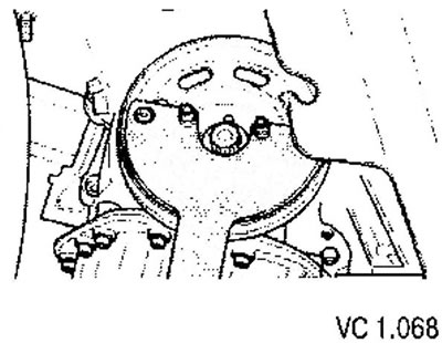
9. Remove the poly V-belt pulley. To secure the crankshaft toothed pulley, screw in the mounting screw with two washers again.
10. Remove the lower part of the timing belt cover.
11. Install the crossbar with legs as shown in the figure and hang the engine in the mounting position.
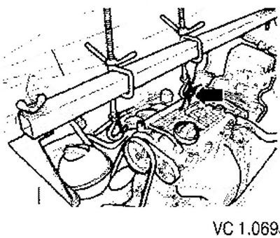
12. Unscrew the filler neck of the windshield washer reservoir.
13. Unscrew the expansion tank of the cooling system and move it to the side (the hoses remain connected).
14. Loosen screws (A), (B) and (C) from the power unit support on the poly V-belt pulley side and remove the power unit support assembly.
15. Unscrew the engine support from the cylinder head.
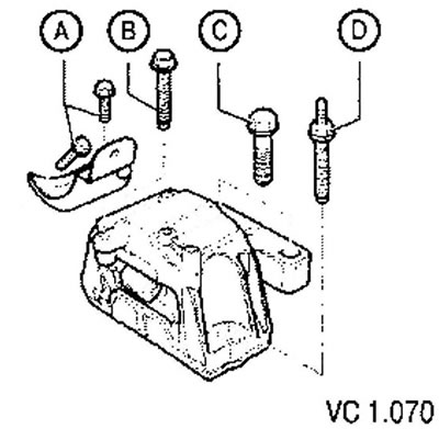
16. Mark the direction of rotation of both timing belts.
17. Remove the main drive toothed belt by following these steps.
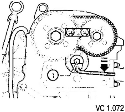
- Loosen the main drive belt tension roller (1) and loosen the toothed belt by turning the tension roller counterclockwise (arrow).
- Loosen the tensioner clamp screw.
- Remove the timing belt.
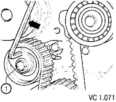
18. Remove the toothed belt of the mating drive, for which perform the following steps.
- Loosen the timing belt tension roller of the coupled drive (1) and loosen the timing belt by turning the tension roller clockwise.
- Remove the timing belt tension roller of the coupled drive.
- Remove the timing belt.
Installation
Initial settings
The pistons should not be at TDC.
The crankshaft timing pulley must be bolted to the crankshaft with a screw and two washers replacing the removed crankshaft pulley.
The camshaft timing pulleys must be secured with a camshaft locking tool through the holes in the camshaft housing and secured against turning, as turning the camshafts may cause the valves to collide with the pistons at top dead center.
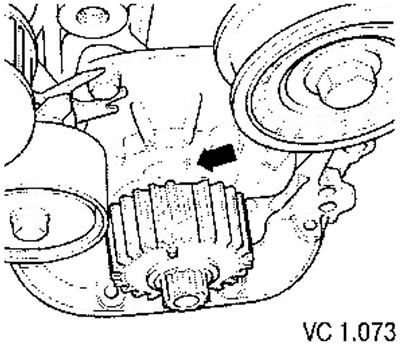
1. Bring the crankshaft to 8MT of the first cylinder. The cut tooth should align with the mark on the oil pump (arrow).
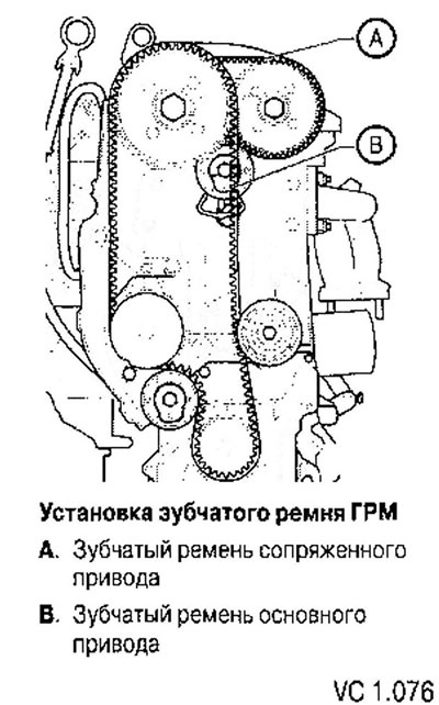
2. Place the toothed belt of the coupled drive clockwise, first from above onto the toothed pulley of the intake camshaft, then onto the toothed pulley of the exhaust camshaft. The loose part of the timing belt should be at the bottom. Observe the direction of travel of the previously used belt.
3. Install the timing belt tension roller as follows.
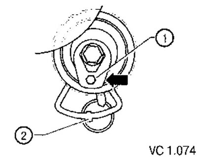
- Turn the tension roller of the mating drive belt with the internal hexagon (1) clockwise towards the indicator window (arrow) (tension roller in a loose position).
- Use the tension roller to pull the lower part of the toothed belt of the coupled drive upwards and tighten the tension roller mounting bolt.
- Tighten the mounting screw by hand. The protrusion of the support plate must enter the hole in the cylinder head (2).
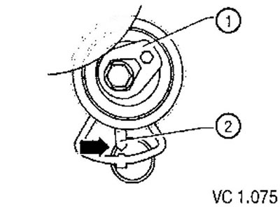
4. Tighten the timing belt by turning the tension roller with the Allen key (1) counterclockwise until the arrow (2) stops above the toe of the support plate in the indicator window (arrow).
Tighten the clamp screw on the tension roller. Tightening torque: 20 Nm.
The camshafts must remain locked against rotation until the main drive timing belt is installed.
5. Install the main drive timing belt, observing the installation direction counterclockwise, first onto the water pump pulley, through the tension roller, crankshaft timing pulley, fixed roller and intake camshaft timing pulley. A used belt must be installed in accordance with the previously applied direction of travel mark.
6. If the tension roller was previously removed, it must be installed as follows.
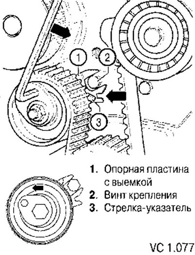
- Turn the main drive belt tension roller with the internal hex key counterclockwise to the indicated position (arrow).
- Tighten the mounting bolt by hand. The recess in the support plate (1) must fit around the head of the mounting screw (2).
- Tighten the timing belt by turning the tension roller in the direction of the arrow until the arrow (3) is positioned over the slot in the support plate (arrow).
- Tighten the clamp screw on the tension roller. Tightening torque: 20 Nm.
(The text is copied from this portal VWmanual)
7. Remove the locking pin from the camshaft sprockets.
8. Turn the crankshaft twice in the direction of engine rotation until it again stops at the TDC position of the first cylinder.
9. After this, it is necessary to check the position of the toothed belts and tension rollers again.
10. If necessary, both timing belts must be re-tensioned.
11. Install the lower part of the timing belt cover.
12. Install the crankshaft poly V-belt pulley. In this case, it is necessary to take into account the following.
- The crankshaft pulley mounting screw and the crankshaft toothed pulley must be replaced with a new one.
- When installing the poly V-belt pulley, you need to ensure that the toothed belt pulley is secured.
- Observe the tightening method of a new bolt, lightly lubricated on the threads.
- Bolt the engine mount to the cylinder head. Tightening torque: 50 Nm.
- Install the powertrain support.
- Install the upper timing belt guard.
- Install the poly V-belt. When installing the poly V-belt, ensure it is correctly positioned on the pulleys.
- Install soundproofing casing.
- Install the front right wheel arch liner.
- Screw on the expansion tank of the cooling system.
Engine with letter designation BSA: Install the air filter housing.
Engine with letter designation BUD: Install the air cleaner housing.
Visitor comments