
Disassembly
1. Loosen the alternator belt tension, remove the belt, then remove the alternator.
2. Remove the toothed belt.
3. Remove the valve cover from the cylinder head, evenly loosen the cylinder head bolts in the reverse order shown in rice. D:20.
4. On models with a manual transmission, remove the flywheel and clutch as described in chapter "Clutch and manual transmission". Remove the intermediate plate located on the mounting sleeves on the rear of the engine.
5. On models with automatic transmission, remove the drive plate along with the reinforcement and adjustment plates (rice. D:31). Remove the intermediate plate from the rear of the engine.
6. Turn away bolts of fastening of the basis of the oil filter and remove the filter together with a replaceable element from the block of cylinders. Disconnect the oil cooler from the oil filter (in the presence of).
7. Remove the dipstick, turn the cylinder block over and remove the oil pan.
8. Turn out two bolts of fastening of the oil pump with an oil pick-up and remove all knot.
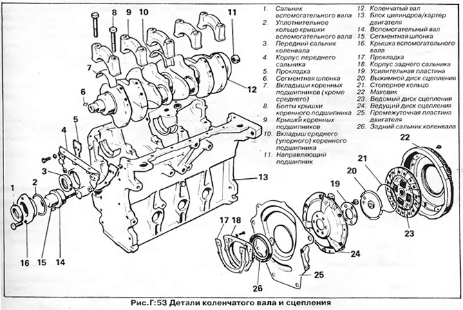
9. Turn away bolts of fastening and remove the case of a back epiploon of a cranked shaft.
10. Remove the pulley and crankshaft sprocket. Remove the auxiliary shaft sprocket.
11. Remove the cooling pump housing from the cylinder block.
12. Remove the fuel pump and ignition distributor.
13. Turn out two bolts of fastening of a cover of an auxiliary shaft, remove a cover from the forward party of the block of cylinders and take out an auxiliary shaft.
14. Turn away bolts and remove the case of a forward epiploon of a cranked shaft from the block of cylinders.
15. For each connecting rod in turn:
- A) Rotate the crankshaft until the connecting rod is at bottom dead center.
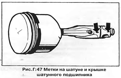
- b) Make sure the connecting rod and connecting rod bearing cap are marked with the cylinder number (pic. D:47).
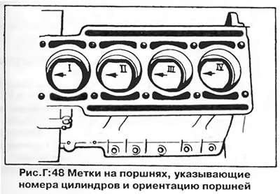
- V) Mark the cylinder number on the piston head, mark the front side of the piston with an arrow (pic. D:48).
- G) Loosen the nuts securing the connecting rod bearing cap, lightly tap the cap, then completely loosen the nuts and remove the connecting rod cap from the connecting rod.
- d) Push the piston and connecting rod assembly up and carefully remove it from the cylinder block.
- e) Remove the connecting rod bearing shells from the cap and connecting rod; mark them if you do not intend to replace the liners.
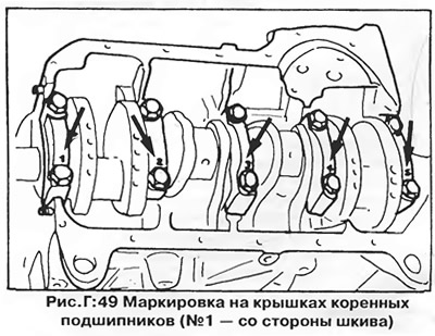
16. Evenly loosen the bolts of the main bearing caps, make sure they are correctly marked and remove the caps. Carefully lift the crankshaft and remove it from the crankcase (pic. D:53).
17. Remove the main bearing shells from the beds in the crankcase and from the covers. Label them if further use of the liners is expected.
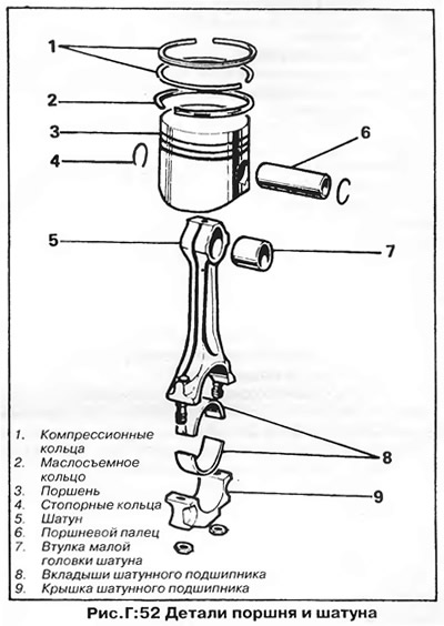
18. If necessary, disassemble the connecting rod and piston assembly in the following order (pic. D:52):
- A) Press out the circlips on both sides of the piston pin hole in the piston.
- b) Press out the piston pin using a suitable drift (preheat the plunger in hot water for a few minutes).
- V) Remove the piston rings towards the piston crown.
Inspection and repair
NOTE: Repair of the cylinder head was described earlier in the section "cylinder head".
Cylinders, pistons, crankshaft and other parts inspect as described in chapter "Engine 1.0/1.3".
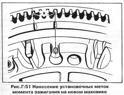
When installing a new flywheel or drive plate, mark it with an ignition timing alignment mark (new flywheels only have a TDC mark - "0"). Using a flexible steel tape, measure the appropriate distance from the center of the TDC mark, as shown in fig. G:51, and do at risk flywheel (notch) triangular file.
- TDC - label "0"
- 7.5 to TDC - X = 16 mm
- 9 to TDC - flywheel - X = 18.5 mm
- 9°to TDC - driving disk AT - X = 21 mm
Setting the ignition timing (initial ignition timing) for various models is given in the section "Technical data".
Assembly
1. Establish loose leaves of radical bearings in bed of the block of cylinders and a cover. Make sure that the lock on each bushing fits correctly into the corresponding recess in the body, the bearings with oil grooves are installed in the cylinder block, and the smooth bearings are installed in the covers. The middle main bearing shells have thrust surfaces because the middle main bearing is thrust and limits the axial movement of the crankshaft.
2. Lubricate the working surface of the liners and the crankshaft main journals with engine oil and carefully lower the crankshaft onto the bearings.
3. Install the main bearing caps in their respective places and tighten the bolts to the torque specified in section "Technical data".
4. Check the end play of the crankshaft. Move the crankshaft all the way forward to select play in one direction, then measure the clearance between the thrust surface of the middle main bearing shell and the crankshaft web with feeler gauges. Axial play should be in the range of 0.07-0.17 mm, the maximum allowable play is 0.25 mm.
5. If the pistons separated from the connecting rods, assemble them as follows:
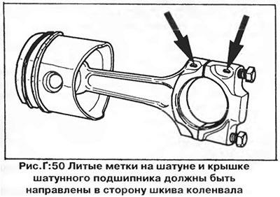
Heat the piston in hot water to 60°C and lubricate the piston pin holes in the connecting rod and piston with graphite grease. Assemble the connecting rod with the piston so that the arrow marked earlier on the piston crown and the cast marks on the connecting rod and cap are on the same side (pic. D:50). Press the piston pin into the piston and secure it with circlips on both sides. Make sure that both circlips are securely engaged in the grooves.
6. Install the piston rings on the piston by sliding them over the top of the piston. The lower compression and oil scraper rings are marked on the surface facing the top of the piston "TOR". Repair top rings have a groove along the upper outer edge to avoid contact of the ring with the ridge (bead), formed in the upper part of the cylinder due to wear. Such rings must be installed with the groove up.
To eliminate the possibility of breakage of the rings and damage to the piston, use a special tool when installing the rings (ring expander - fig. Q:47).
7. For each piston with connecting rod in turn:
- A) Make sure the piston is assembled correctly with the connecting rod.
- b) Turn the piston rings so that their locks are offset from each other by 120° (see chapter "Engine 1.1/1.3").
- V) Lubricate the inside of the cylinder and piston rings liberally with clean engine oil.
- G) Install the piston with the connecting rod in the corresponding cylinder with the arrow on the piston crown towards the crankshaft pulley (pic. D:48).
- d) Compress the piston rings with a special mandrel, as shown in fig. Q:49 per chapter "Engine 1.0/1.3".
Do not try to insert the piston without a mandrel - if the piston is manually installed, the rings may break. Push the piston out of the mandrel and into the cylinder with a hammer handle until the piston crown is slightly below the top edge of the cylinder. Be careful not to damage the crankshaft journal with the connecting rod.
- e) Install the connecting rod bearing shells to the connecting rod and cap. Make sure that the lock in each bush fits securely into the corresponding recess in the bearing bed.
- and) Lubricate the crankshaft journal and liners with engine oil, firmly pull the connecting rod to the neck and install the cover on it.
- h) Make sure the numbers on the connecting rod and cap match and are on the same side.
- And) Install the connecting rod cap with new nuts, tightening them to the torque specified in section "Technical data".
- To) Check the axial play of the connecting rod on the neck using feeler gauges (see section "Technical data").
8. Reassemble the remaining parts in the reverse order of their removal. Install new gaskets and seals (oil seals); tighten all bolts and nuts to the required torque.
Visitor comments