



Contents: Removal ↓ Installation ↓
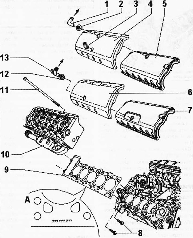
Fig. 2.201. Cylinder head components:
1 - connecting hose (in vehicles with BLE and BWF engines); 2 - sealing cuff (in vehicles with BLE and BWF engines); 3 - holder (in vehicles with BLE and BWF engines); 4 - soundproof cover (in vehicles with BLE and BWF engines); 5 - cylinder head cover (in vehicles with BLE and BWF engines); 6 - soundproof cover (for vehicles with engine letter designations AYH, BKW); 7 - cylinder head cover (for vehicles with engine letter designations AYH, BKW); 8 - bolt 20 Nm; 9 - cylinder head gasket; 10 - cylinder head; 11 - cylinder head bolt; 12 - sealing cuff; 13 - adapter (for vehicles with engine letter designations AYH, BKW).
ATTENTION: The cylinder head and aluminum cylinder block are connected to the crankshaft support rail using anchor bolts. Both cylinder heads must be replaced. Loosening and unscrewing the cylinder head bolts will warp the cylinder block.
NOTE: The components shown here are for the first bank of cylinders. They are mirror images of the components for the second bank of cylinders.
Removal
Remove the engine and gearbox.
Remove the soundproofing cover and cylinder head cover from the cylinder heads.
[The original article is available on the website: www.VWmanual.ru]
Remove the fuel pump and tandem pump from the cylinder heads.
Set the crankshaft to the dead center position of the first cylinder and check the valve timing.
Remove the camshaft drive gears.
Remove the mounting bolts between the timing cover and the cylinder head of the first and second rows of cylinders.
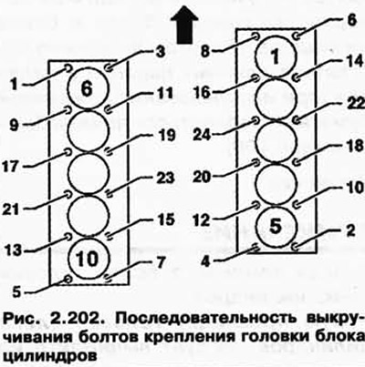
Loosen and remove the cylinder head bolts in the specified sequence (fig. 2.202) points in the direction of travel).
Using an assistant, carefully remove the cylinder heads.
NOTE: Handle the cylinder heads very carefully to avoid damage. Place a clean rag in the cylinders to prevent dirt and sandpaper from getting between the cylinder faces and the pistons. Make sure that no dirt or sandpaper gets into the coolant either.
NOTE: Carefully clean the seating surfaces of the cylinder head and block. There should be no long scratches or burrs (when using sandpaper, its grain size should be at least 100).
Installation
NOTE: Always replace the cylinder head bolts. The new cylinder head gasket should be removed from the packaging immediately before installation.
NOTE: Install a cylinder head gasket with the same "Dlcke/Thickness" index as the removed gasket.
NOTE: Handle the gasket with extreme care. Damage to the silicone layer and corrugated connections will result in loss of sealing.
Before installing the cylinder heads, set the crankshaft to the dead center position of the first cylinder.
Rotate the crankshaft against the direction of rotation of the engine shaft until all pistons are evenly positioned below dead center.
Install the cylinder head gasket.
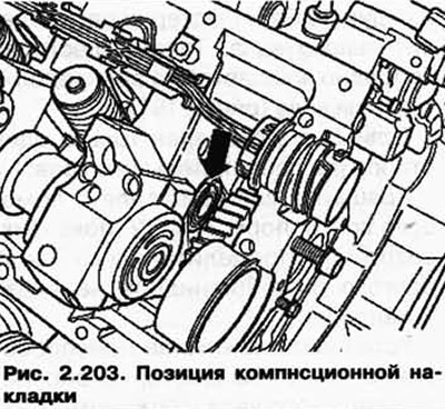
Install the cylinder head, taking into account the position of the compensation lining (fig. 2.203), install the cylinder head bolts with washers and tighten by hand.
CAUTION: All cylinder head bolts except (by tightening sequence) number 1, 2, 17 and 19 must be fitted with groove washers.
Tighten the cylinder heads in four stages in the specified tightening sequence ((fig. 2.204) shows the direction of movement).
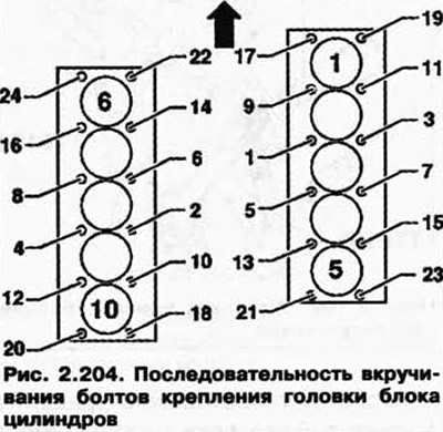
1 - Tighten with a torque wrench:
- stage 1 = 30 Nm;
- stage 2 = 60 Nm.
2 - Then turn with a regular key:
- step 3 = turn 1/2 turn further (180°);
- step 4 = turn an additional 1/2 turn (180°).
Install the camshaft drive gears.
Adjust the valve timing.
Visitor comments