
Removing
Remove the gearbox.
Insert the screw release support.
Loosen the screws little by little, crosswise.
Remove pressure plate and clutch disc.
Installation
Installation is carried out in the reverse order, paying attention to the following points.
Note: Replace pressure plate and clutch disc only together. Identify pressure plate and clutch plate by engine code.
Note: The adjusting ring of the clutch pressure plate with automatic working air gap adjustment must only be checked or, if necessary, retracted to its original position in new LuK clutches.
Note: Check if there are fitted bushings for centering the engine/gearbox in the cylinder block, insert them if necessary.
Note: Lack of fitted bushings results in shifting difficulties, clutch problems and hence gearbox noise (crackling in drive wheels).
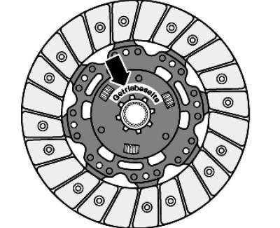
Pic. 3.30. Installation position of the clutch disc
Inscription «Gearbox side» towards the gearbox (pic. 3.30).
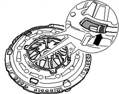
Checking the ends of the diaphragm spring
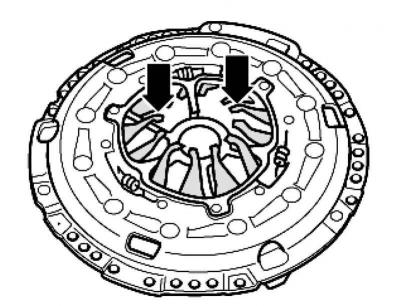
Pic. 3.34. Checking the ends of the diaphragm spring
Check the ends of the diaphragm spring (pic. 3.34).
The diaphragm spring is allowed to wear up to half of its thickness.
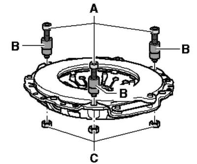
Checking keyed and riveted connections
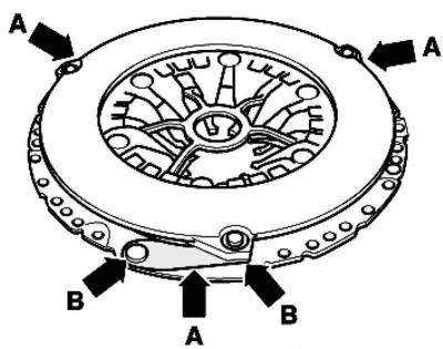
Pic. 3.35. Checking keyed and riveted connections
Check for damage to the keyed connections A, as well as the tightness of the fastening of the connections on the rivets B (pic. 3.35).
Note: Replace clutch discs and pressure plates with damaged or missing rivet connections.
Note: Only replace clutch disc and pressure plate together.
Note: Identify pressure plate and clutch plate by engine code.
Note: To reduce odor in the event of a burnt clutch, the clutch cap, as well as the flywheel and engine side of the transmission, must be thoroughly cleaned.
Note: Clean the input shaft gear and, if using a clutch disc, the hub gear, remove any corrosion and apply a very thin layer of clutch disc gear grease to the gear. Then move the clutch disc in one direction and the other until the hub can easily walk on the shaft. Be sure to remove excess grease.
Note: Pressure plates are corrosion protected and greased. They can only clean the working surface, otherwise the service life of the clutch will be significantly reduced.
Note: The working surface of the pressure plate and the lining of the clutch plate must fit snugly against the flywheel. Only then can you insert the fixing screws.
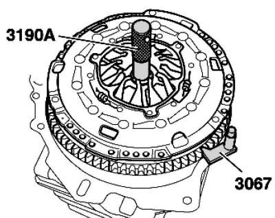
Pic. 3.36. Support installation
When installing, insert the support (pic. 3.36).
Slide the pressure plate onto the dowel pins.
Use a centering rod to center the clutch disc.
Hand-tighten all screws evenly until the head of the screw is in contact with the pressure plate.
Tighten the screws progressively in a criss-cross pattern so as not to damage the centering holes of the pressure plate and the centering pins of the dual-mass flywheel.
Install the gearbox.
Checking and, if necessary, retracting the adjusting ring of the self-aligning pressure plate (only on new LuK clutches)
The work steps described below apply only to LuK clutches.
The prerequisite is the installation of a new pressure plate and a new clutch plate.
When installing a used pressure plate and clutch plate, it is not allowed to return the adjusting ring to its original position.
In clutches «Sachs» it is impossible to withdraw the pressure plate to its original position
Pic. 3.37. The position of the adjusting ring in the pressure plate
When installing a new pressure plate and clutch plate, check the position of the adjusting ring in the pressure plate (pic. 3.37).
Adjusting ring must be pulled back as far as it will go
In this case, the springs are compressed to «touching adjacent turns»
Otherwise, due to the reduced clutch pressure, the clutch disc will be subject to increased wear.
If the springs are not compressed to «touching adjacent turns», it is necessary to unscrew the adjusting ring to its original position
Pic. 3.38. Pressure plate mounting bolts
Insert, as shown in Figure 3.38, 3 pressure plate mounting bolts, M6x35, A offset by 120°into the pressure plate mounting holes.
B - a spacer about 20 mm high, for example: a socket wrench SW 10 for a 1/4 inch drive.
Screw 3 nuts C onto screws A.
Lay the pressure plate in the production press so that it rests with only 3 bolt heads.
Center the thrust washer in the center of the pressure plate.
In the next operation, do not apply excessive force, otherwise the adjusting ring forks may be destroyed
Attach two screwdrivers to the adjusting ring pins.
Press down on the pressure plate until the adjusting ring can move.
Working evenly with both screwdrivers, move the adjusting ring in the direction of the arrow to the rear until it stops.
Hold the adjusting ring in the stop position and at the same time reduce the pressure of the press so that the adjusting ring remains in this position.
Visitor comments