
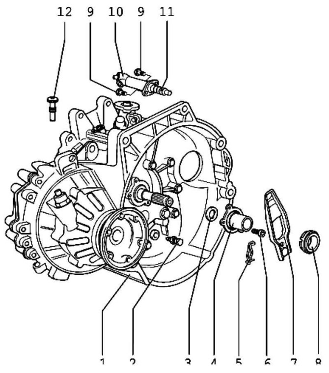
Pic. 3.26. Clutch Release Mechanism: 1 - gearbox; 2 - ball pin, 25 Nm; 3 - lip seal for the input shaft; 4 - guide sleeve; 5 - spring latch; 6 - bolt, tightening torque 20 Nm; 7 - clutch release lever; 8 - release bearing; 9 - bolt with shoulder, 20 Nm; 10 - working cylinder; 11 - pusher; 12 - mounting screw
Install the air filter housing assembly if necessary.
Connect the ground wire to the battery.
Note: If a mounting screw is not available, an M8x35 screw can be used.
Remove and install clutch release lever with release bearing
Remove spring 1.
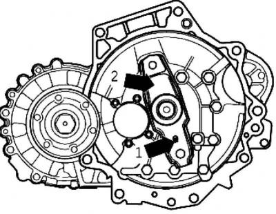
Pic. 3.27. Clutch Release Lever
Remove clutch release lever 2 and release bearing (pic. 3.27).
Install in reverse order.
Removal and installation of release bearing
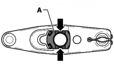
Pic. 3.28. Locking tabs on the back of the clutch release lever
Squeeze the locking tabs on the reverse side of the clutch release lever and remove the release bearing A from it (pic. 3.28).
To install, insert clutch release bearing A into the clutch release lever until the latches engage.
Visitor comments