
English Русский
Български
Беларускі
Український
Српски
Hrvatski
Română
Polski
Slovenský
Magyar
  |  Articles  |  Sitemap  |  Contacts  |    |
Car maintenance Ford Car maintenance Hyundai Car maintenance Chevrolet Car maintenance BMW Car maintenance Audi Car maintenance Opel Car maintenance AvtoVAZ
VWmanual.ru


Main   Passat   Golf   Polo   Touareg   Tiguan   Sharan   Transporter   Others  
Passat B2 (1981-1988) Passat B3 (1988-1993) Passat B4 (1988-1996) Passat B5 (1996-2005) Passat B6 (2005-2010)

Checking/adjusting idle speed and CO content Digifant (VW Passat B3)

  • Main
  • Passat
  • Passat B3
  • Power unit
  • Petrol injection system
  • Checking/adjusting idle speed and CO content Digifant
            0


Contents: Digifant injection system, engines…↓ Engines with catalytic converter…↓

Digifant injection system, engines with designations ABF, PF, PB, PG, 2E


Caution: Idle speed, CO content and ignition timing must be checked and adjusted together. In engines with a regulated catalytic converter, the oxygen sensor remains connected during testing.


Prerequisite for checking: the exhaust system must be tight.

Warm up the engine until the engine oil temperature is not lower than +80°C.

Turn off all electrical consumers, as well as the air conditioning system.

If the fuel lines have been disconnected or replaced, before checking the engine shaft must be brought to a speed of 3000 1/min several times, and then the engine must be left to idle for at least two minutes.

Attention: Connect the devices only when the ignition is off.


Check the ignition timing, see chapter "Ignition system".

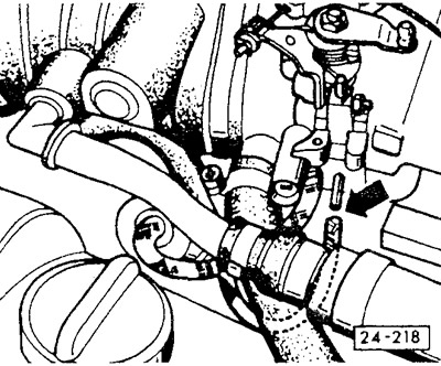
Make sure that the crankshaft speed stabilization system valve works when the engine is idling. To do this, turn on the ignition and place your hand on the valve. The valve should vibrate and buzz audibly. The valve is located above the cylinder head, next to the throttle valve pipe, see above.

Connect the crankshaft speed meter according to the service manual.
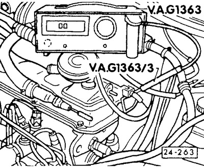
Connect the crankshaft speed meter according to the service manual.


Engine with adjustable catalytic converter (designations ABF, PF, PB, PG, 2E): connect the CO measuring device to the CO sampling pipe in the engine compartment. The sampling pipe is welded to the front exhaust pipe and is usually closed with a light blue cap.


Attention: Securely attach the measuring instrument hose to the sampling tube and ensure that the connection is tight.


112 hp engine. (rV designation): connect the CO measuring device to the final outlet pipe.
112 hp engine. (rV designation): connect the CO measuring device to the final outlet pipe.


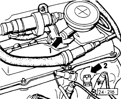
Disconnect the crankcase ventilation hose at the pressure regulating valve -arrow 1-. Close the hose, for example, with a plug, a screwdriver handle or by pinching. Engine with the designation ABF, 2E: disconnect the double hose at the pressure regulating valve and close only the opening of the hose leading to the intake air hose. If there are two separate crankcase ventilation hoses, disconnect the ventilation hose from the intake air hose and seal the opening in the intake air hose with a plug. For this purpose, you can use the inspection hole cap for setting the TDC position, see Chapter "Ignition system".

Start the engine and let it idle.

After 1 minute, disconnect the temperature sensor plug (blue) (arrow 2). Engine 2E up to 7/92: After the cooling system fan has already been switched on once, disconnect the coolant temperature sensor plug with the throttle valve closed.

Give the gas three times, increasing the crankshaft speed to a value greater than approximately 3000 1/min. Then let the engine idle.


Attention: During testing and adjustment work, the cooling system fan must not rotate.

Attention: During testing and adjustment work, the cooling system fan must not rotate.


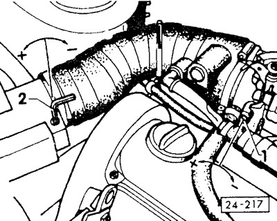
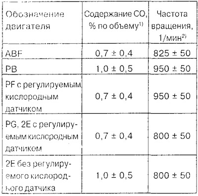
Check the crankshaft speed and CO content when idling. If necessary, adjust the above parameters to the specified values by alternately turning the speed adjusting screw "1" and the CO content adjusting screw "2".
Check the crankshaft speed and CO content when idling. If necessary, adjust the above parameters to…


1) The specified CO content value is valid up to an altitude of 300 m above sea level. If the adjustment location is above 300 m, then for every subsequent 100 m of altitude it is necessary to add 0.2% by volume. Example: at an altitude of 700 m above sea level, the RV engine should have a CO content of 1.8 ±0.5% by volume.

2) The temperature sensor plug (blue) is disconnected.

Reconnect the blue plug of the temperature sensor and secure it.

Give it gas three times, then let the engine idle.

Check the crankshaft speed and CO content again when idling. The crankshaft speed should now decrease to 800 ±50 1/min.

Note: For engines with a regulated catalytic converter, the CO content after connecting the temperature sensor plug is regulated regardless of the altitude to a value of 0.7 ±0.4% by volume.

Engines with catalytic converter (designation PF, PG and 2E up to 7/92)


Engines with catalytic converter (designation PF, PG and 2E up to 7/92)


Checking the oxygen sensor adjustment. To do this, disconnect the hose from the pressure regulator at the throttle valve pipe and close the connecting element. The CO content should increase briefly and then decrease again. This indicates that the oxygen sensor adjustment is in good order. Otherwise, check the oxygen sensor adjustment. Put the hose back on.

Connect the crankcase ventilation hose to the pressure control valve or, respectively, to the intake air hose and secure with a clamp.

Note: If the CO content has now increased, the reason is not incorrect adjustment, but rather the enrichment of the combustible mixture due to the influx of gasoline vapors from the crankcase, where gasoline gets mainly during short-distance trips.


During long, continuous trips, the proportion of gasoline in the engine oil decreases, and the CO content in the exhaust gases returns to normal. This can also happen quickly after about a 30-minute trip or another oil change.

Measuring instruments must be switched off when the ignition is off.

Reconnect all disconnected hoses and wires.

This article is available at russian, bulgarian, belarusian, ukrainian, serbian, croatian, romanian, polish, slovak, hungarian
The text has been checked: Medvedeva Elena

Share information:

Previous articles
Injection system Digifant / Simos
Electrical test of the Mono-Jetronic injection system
Checking the intake manifold heating system
Checking the temperature sensor
Checking the oxygen sensor
Checking the throttle potentiometer
Next articles
Checking the regulation of the oxygen sensor Digifant
Checking the Idle Speed Increase Valve Digifant
Checking the forced idle and enrichment switch with the throttle fully open
Removal and installation / checking of Digifant/Simos valve injectors
Simos injection system since 10/94
Electrical test of the Digifant injection system


Similar articles from other manuals for VW cars:
Adjusting the idle speed parameters of the Digijet injection… Golf 2 (1984-1993)
Checking/adjusting idle speed/ignition timing/CO content Polo 4 (2001-2009)
Checking and adjusting the position of the pump-injector pistons… Touareg 1 (2002-2006)
Checking the operation of the intake manifold flap Tiguan 1 (2007-2015)
Checking the engine oil level and replacing it Sharan 1 (1995-2000)
Checking and adjusting idle speed and CO content Transporter T3 (1979-1992)
Checking and adjusting idle speed Beetle (1960-1986)
Link to this page in different formats


Visitor comments


No comments yet


How much will 27 + 47 =


Passat B6 
  • General information
  • User manual
  • Maintenance
  • Petrol engine 1.6L
  • Engine repair
  • Cooling and lubrication system
  • Fuel injection system
  • Petrol engine 2.0L
  • Engine repair
  • Lubrication system
  • Cooling system
  • Fuel and exhaust systems
  • Diesel engine 2.0L
  • Engine repair
  • Cooling and lubrication system
  • Fuel and exhaust systems
  • Transmission
  • Clutch
  • Mechanical gearbox
  • Automatic gearbox
  • Drive shafts
  • Chassis
  • Wheels and tires
  • Car suspension
  • Steering
  • Brake system
  • Body
  • Exterior (external elements)
  • Electrical equipment
  • Power devices
  • Lighting and appliances
  • Electrical circuits
Passat B5 
  • General information
  • User manual
  • Weekly checks
  • Maintenance
  • Power unit
  • Engine repair
  • Cooling system
  • Fuel system (petrol)
  • Fuel system (diesel)
  • Engine management
  • Exhaust system
  • Transmission
  • Clutch
  • Car gearbox
  • Drive shafts
  • Chassis
  • Car suspension
  • Wheels and tires
  • Steering
  • Brake system
  • Body
  • Exterior (external elements)
  • Interior (internal elements)
  • Doors and covers
  • Ventilation and heating
  • Electrical equipment
  • Power devices
  • Lighting and appliances
  • Electrical circuits
Passat B4 
  • General information
  • User manual
  • Maintenance
  • Technical data
  • 8-valve engine
  • Engine repair
  • Cooling and lubrication system
  • Supply system
  • Ignition system
  • Fuel injection «Mono-Jetronic»
  • Control system «Mono-Motronic»
  • Control system «Digifant»
  • Control system «Simos»
  • 16-valve engine
  • Engine repair
  • Cooling and lubrication system
  • Fuel injection «K-Jetronic»
  • Control system «KE-Motronic»
  • Control system «Digifant»
  • Diesel engine
  • Engine repair
  • Cooling and lubrication system
  • Power and control system
  • Turbocharging system
  • Digital control system
  • Transmission
  • Clutch
  • Manual gearbox
  • Hydromechanical gearbox
  • Front wheel drive
  • Chassis
  • Car suspension
  • Steering
  • Brake system
  • Body
  • Body elements
  • Electrical equipment
  • Power devices
  • Lighting and appliances
  • Electrical circuits
Passat B3 
  • General information
  • User manual
  • Driving Tips
  • Maintenance instructions
  • Technical data
  • Power unit
  • Engine repair
  • Ignition system
  • Lubrication system
  • Cooling system
  • Supply system
  • Petrol injection system
  • Diesel engine
  • Exhaust system
  • Transmission
  • Clutch
  • Car gearbox
  • Chassis
  • Suspension
  • Steering
  • Brake system
  • Wheels and tires
  • Body
  • Exterior
  • Interior
  • Heating system
  • Electrical equipment
  • Power devices
  • Lighting system
  • Equipment and devices
  • Wiper system
  • Electrical circuits
Passat B2 
  • General information
  • Introduction to instructions
  • User manual
  • Power unit
  • Engines 4-cylinder FZ
  • Engines 4-cylinder
  • Engines 5-cylinder
  • Transmission
  • Clutch
  • Four-speed gearbox
  • Five-speed gearbox
  • Hydromechanical gearbox
  • Front wheel drive
  • Chassis
  • Front suspension
  • Rear suspension
  • Steering
  • Brake system
  • Body
  • Body elements
  • Electrical equipment
  • Equipment and devices
  • Electrical circuits
VWmanual.ru © 2016-2026 | Mobile version | News and articles | Sitemap: EN BG BY UA RS HR RO PL SK HU | Write message | Site search
Passat B2 • Passat B3 • Passat B4 • Passat B5 • Passat B6 • Golf 1, diesel • Golf 1, petrol • Golf 2, petrol • Golf 2 • Golf 3 • Golf 4 • Golf 5 • Polo 3 • Polo 4 • Touareg 1 • Tiguan 1 • Sharan 1 • Transporter T3 • Transporter T4 • LT 28 • LT 2D • Beetle • Caddy 3 •
Our website uses cookies to ensure functionality and convenience.