
English Русский
Български
Беларускі
Український
Српски
Hrvatski
Română
Polski
Slovenský
Magyar
  |  Articles  |  Sitemap  |  Contacts  |    |
Car maintenance Ford Car maintenance Hyundai Car maintenance Chevrolet Car maintenance BMW Car maintenance Audi Car maintenance Opel Car maintenance AvtoVAZ
VWmanual.ru


Main   Passat   Golf   Polo   Touareg   Tiguan   Sharan   Transporter   Others  
Passat B2 (1981-1988) Passat B3 (1988-1993) Passat B4 (1988-1996) Passat B5 (1996-2005) Passat B6 (2005-2010)

Removal and installation the steering column switch (VW Passat B3)

  • Main
  • Passat
  • Passat B3
  • Electrical equipment
  • Equipment and devices
  • Removal and installation the steering column switch
            0


Contents: Removal ↓ Installation ↓ Location of the terminals of the…↓ Terminal locations on steering shaft…↓

Removal


If equipped, remove the airbag assembly, see chapter "Steering".
If equipped, remove the airbag assembly, see chapter «Steering».


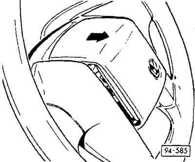
Steering wheel without airbag: remove the steering wheel cover. To do this, lift the cover from below and remove it in the direction of the arrow.
Steering wheel without airbag: remove the steering wheel cover. To do this, lift the cover from…


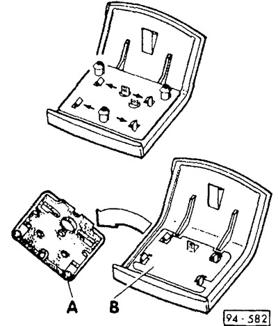
If necessary, remove the horn button by pressing the locking tabs in the direction of the arrows and removing the contact plate.

Note: the button consists of two contact plates "A" and "B", separated from each other. When the button is pressed, the plates are pressed against each other with uninsulated areas.

Note: the button consists of two contact plates «A» and «B», separated from each other. When the…


Positive voltage is supplied to the button through the spring contact of the switch on the steering column and to the contact ring under the steering wheel.


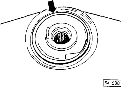
Remove the steering wheel, see chapter "Steering".

Unscrew the 2 mounting screws and remove the instrument panel bezel.

Unscrew the 2 screws securing the steering column trim at the bottom.

(The information is posted on this website vwmanual.ru)
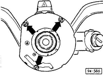
Unscrew the 2 screws securing the steering column trim at the bottom.


Remove the mounting screws.

Disconnect the plug connectors at the switch on the steering column.

Remove the switch from the steering column.

Installation


Place the switch on the steering column.

Connect the multi-pin plug connector.

Screw on the steering column trim.

Screw on the switch.

Place and screw on the instrument panel bezel.

Install the steering wheel, see chapter "Steering".

Press and secure the steering wheel cover.

Check the operation of the sound signal.

Location of the terminals of the switch on the steering column


A - ignition and starter switch
  • 1 — terminal 15
  • 2 — terminal X
  • 3 — terminal 50
  • 4 — terminal 30
  • 5 — terminal SU
  • 6 — terminal P

B - plug connector, 5-pin
  • 1 - Windscreen wiper switch, terminal 53b
  • 2 - windshield wiper switch, terminal 53a
  • 3 - windshield wiper switch, terminal 53
  • 4 - windshield wiper switch, terminal 53e
  • 5 - Windscreen wiper switch, terminal J

C - plug connector, 5-pin

  • 1 - Hazard warning light switch, terminal 49
  • 2 - manual switch for low beam and intermittent light signal, terminal 56b
  • 3 - manual switch for low beam and intermittent light signal, terminal 56
  • 4 - manual switch for low beam and intermittent light signal, terminal 56a
  • 5 - manual switch for low beam and intermittent light signal, terminal 30

D - Plug connector, 4-pin
  • 1 - Windscreen wiper switch, terminal L
  • 2 - windshield wiper switch, terminal T
  • 3 - windscreen wiper switch, terminal 31
  • 4 — hazard warning light switch, terminal 15

E - Plug connector, 7-pin
  • 1 - Horn drive, terminal 71
  • 2 - hazard warning light switch, terminal 49a
  • 3 - direction indicator switch, terminal L
  • 4 - Parking light switch, terminal PL
  • 5 - Parking light switch, terminal P
  • 6 - Parking light switch, terminal PR
  • 7 - direction indicator switch, terminal R


Terminal locations on steering shaft housing for MFA and GRA
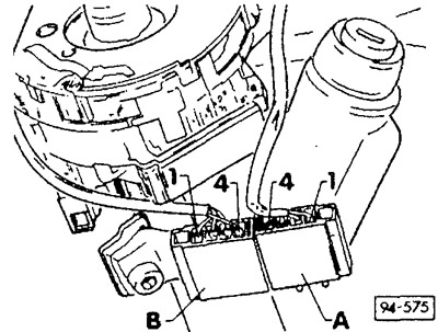


Terminal locations on steering shaft housing for MFA and GRA


A - Plug connector, 4-pin, universal indicator switch (MFA)
  • 1 — terminal 31
  • 2 - action (Mode)
  • 3 — storage switch (Memory)
  • 4 - erase (Reset - cancel)

B - Plug connector, 4-pin, cruise control system (GRA) switch
  • 1 - turn on
  • 2 - reception
  • 3 - accumulation (FIX)
  • 4 — terminal 30

This article is available at russian, bulgarian, belarusian, ukrainian, serbian, croatian, romanian, polish, slovak, hungarian
The text has been checked: Medvedeva Elena

Share information:

Previous articles
Replacing LEDs
Checking the voltage stabilizer
Location of instrument panel terminals
Removal and installation the printed circuit board
Removal and installation the tachometer shaft cover
Removal and installation the instrument panel
Next articles
Removal and installation the steering wheel shaft lock housing
Removal and installation steering column trim
Removal and installation the ignition lock cylinder/steering wheel shaft
Removal and installation radio
Entering the radio code
Removal and installation the antenna


Similar articles from other manuals for VW cars:
Ignition Switch/Steering Column Lock Golf 1 (1974-1984, petrol)
Steering column multifunction switch Polo 4 (2001-2009)
Steering column switch for headlights and turn signals Touareg 1 (2002-2006)
Removal and installation the steering column switch block trim Tiguan 1 (2007-2015)
Checking the Power Steering Fluid Level Sharan 1 (1995-2000)
Steering Wheel Combination Switch — Design Description Transporter T4 (1990-2003)
Removal and installation the steering column switch panel trim Caddy 3 (2003-2010)
Link to this page in different formats


Visitor comments


No comments yet


How much will 11 + 11 =


Passat B6 
  • General information
  • User manual
  • Maintenance
  • Petrol engine 1.6L
  • Engine repair
  • Cooling and lubrication system
  • Fuel injection system
  • Petrol engine 2.0L
  • Engine repair
  • Lubrication system
  • Cooling system
  • Fuel and exhaust systems
  • Diesel engine 2.0L
  • Engine repair
  • Cooling and lubrication system
  • Fuel and exhaust systems
  • Transmission
  • Clutch
  • Mechanical gearbox
  • Automatic gearbox
  • Drive shafts
  • Chassis
  • Wheels and tires
  • Car suspension
  • Steering
  • Brake system
  • Body
  • Exterior (external elements)
  • Electrical equipment
  • Power devices
  • Lighting and appliances
  • Electrical circuits
Passat B5 
  • General information
  • User manual
  • Weekly checks
  • Maintenance
  • Power unit
  • Engine repair
  • Cooling system
  • Fuel system (petrol)
  • Fuel system (diesel)
  • Engine management
  • Exhaust system
  • Transmission
  • Clutch
  • Car gearbox
  • Drive shafts
  • Chassis
  • Car suspension
  • Wheels and tires
  • Steering
  • Brake system
  • Body
  • Exterior (external elements)
  • Interior (internal elements)
  • Doors and covers
  • Ventilation and heating
  • Electrical equipment
  • Power devices
  • Lighting and appliances
  • Electrical circuits
Passat B4 
  • General information
  • User manual
  • Maintenance
  • Technical data
  • 8-valve engine
  • Engine repair
  • Cooling and lubrication system
  • Supply system
  • Ignition system
  • Fuel injection «Mono-Jetronic»
  • Control system «Mono-Motronic»
  • Control system «Digifant»
  • Control system «Simos»
  • 16-valve engine
  • Engine repair
  • Cooling and lubrication system
  • Fuel injection «K-Jetronic»
  • Control system «KE-Motronic»
  • Control system «Digifant»
  • Diesel engine
  • Engine repair
  • Cooling and lubrication system
  • Power and control system
  • Turbocharging system
  • Digital control system
  • Transmission
  • Clutch
  • Manual gearbox
  • Hydromechanical gearbox
  • Front wheel drive
  • Chassis
  • Car suspension
  • Steering
  • Brake system
  • Body
  • Body elements
  • Electrical equipment
  • Power devices
  • Lighting and appliances
  • Electrical circuits
Passat B3 
  • General information
  • User manual
  • Driving Tips
  • Maintenance instructions
  • Technical data
  • Power unit
  • Engine repair
  • Ignition system
  • Lubrication system
  • Cooling system
  • Supply system
  • Petrol injection system
  • Diesel engine
  • Exhaust system
  • Transmission
  • Clutch
  • Car gearbox
  • Chassis
  • Suspension
  • Steering
  • Brake system
  • Wheels and tires
  • Body
  • Exterior
  • Interior
  • Heating system
  • Electrical equipment
  • Power devices
  • Lighting system
  • Equipment and devices
  • Wiper system
  • Electrical circuits
Passat B2 
  • General information
  • Introduction to instructions
  • User manual
  • Power unit
  • Engines 4-cylinder FZ
  • Engines 4-cylinder
  • Engines 5-cylinder
  • Transmission
  • Clutch
  • Four-speed gearbox
  • Five-speed gearbox
  • Hydromechanical gearbox
  • Front wheel drive
  • Chassis
  • Front suspension
  • Rear suspension
  • Steering
  • Brake system
  • Body
  • Body elements
  • Electrical equipment
  • Equipment and devices
  • Electrical circuits
VWmanual.ru © 2016-2026 | Mobile version | News and articles | Sitemap: EN BG BY UA RS HR RO PL SK HU | Write message | Site search
Passat B2 • Passat B3 • Passat B4 • Passat B5 • Passat B6 • Golf 1, diesel • Golf 1, petrol • Golf 2, petrol • Golf 2 • Golf 3 • Golf 4 • Golf 5 • Polo 3 • Polo 4 • Touareg 1 • Tiguan 1 • Sharan 1 • Transporter T3 • Transporter T4 • LT 28 • LT 2D • Beetle • Caddy 3 •
Our website uses cookies to ensure functionality and convenience.