



Contents: Multi-pin plug connector for…↓ Left signaling unit ↓ Right signaling unit ↓ Multi-pin connector for fuel,…↓ Multi-pin plug connector for…↓ Analog Clock Multi-Pin Plug Connector ↓ Multi-pin digital clock plug…↓ Multi-pin plug connector of…↓
Up to 7/90
Multi-pin plug connector for instrument cluster
Note: To check the multi-pin connector on the printed circuit board, you only need to remove the instrument on the left; the instrument panel itself does not need to be removed.
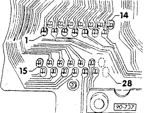
1 - outside air temperature sensor, ground *
2 - not used
3 — terminal 31, ground *
4 - MFA Drive Switch (Reset - Cancel) *
5 — terminal 31, ground *
6 - MFA storage switch (Memory-memory) *
7 - speed signal from the Hall sensor or inductive sensor
8 - hydraulic switch 1.8 bar
9 - hydraulic switch
10 — terminal 1 / terminal W
11 - terminal 30, plus
12 — terminal 58b, lighting
13 — terminal 15
14 - not used
15 - Call button for MFA (Mode-mode) *
16 — terminal 61
17 — oil temperature sensor *
18 — dual-circuit and handbrake system indicator/seat belt status indicator
19 - outside air temperature sensor, signal
20 — glow plug warm-up time indicator
21 — fuel reserve indicator
22 — vehicle self-diagnosis indicator
23 - coolant temperature indicator
24 — direction indicator
25 — high beam indicator
26 - not used
27 - no terminal
28 - no terminal
*) only for universal indicating instrument (MFA)
Left signaling unit
Attention: When installing LEDs, be sure to observe polarity.
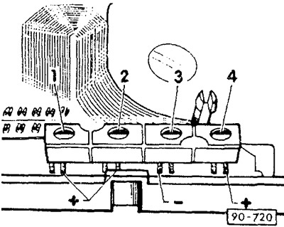
1 - not used
2 - oil pressure indicator (red), LED
3 - high beam indicator (blue), incandescent lamp
4 - indicator (green), LED
Right signaling unit
Attention: When installing LEDs, be sure to observe polarity.
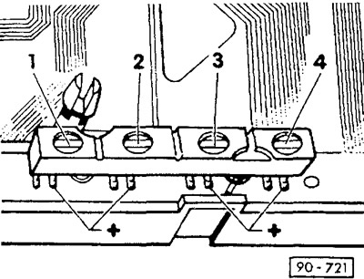
1 — brake control indicator (red), LED seat belt status indicator (red), LED
2 - generator indicator (red), LED
3 — glow plug control indicator (yellow), LED
4 - vehicle self-diagnosis indicator
Multi-pin connector for fuel, temperature and low coolant level indicators
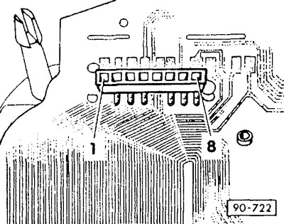
1 - not used
2 — fuel gauge sensor
3 - coolant temperature gauge sensor
4 — terminal 15
5 - not used
6 - not used
7 — terminal 31, ground
8 — output voltage of the voltage stabilizer, 9.5-10.5 V
Multi-pin plug connector for tachometer and oil pressure indicator control unit
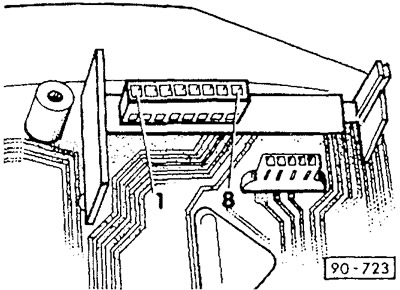
1 — terminal 1 / terminal W
2 — terminal 31, ground
3 - oil pressure indicator
4 — terminal 15
5 - tachometer output signal
6 - not used
7 - hydraulic switch 1.8 bar/1.4 bar
8 - 0.3 bar hydraulic switch
Analog Clock Multi-Pin Plug Connector
The original can be seen on the portal: vwmanual.ru
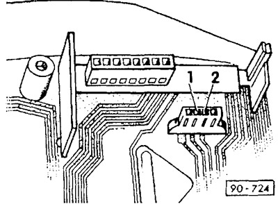
1 - terminal 30, plus
2 — terminal 31, ground
Multi-pin digital clock plug connector
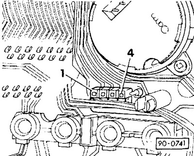
1 - terminal 15 (for MFA)
2 - terminal 58b, lighting
3 - terminal 30, plus
4 — terminal 31, ground
Multi-pin plug connector of universal indicating device
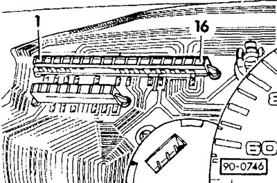
1 — call button for MFA (Mode)
2 - oil temperature sensor
3 - outside air temperature sensor, signal
4 — terminal 15
5 - not used
6 - outside air temperature sensor, ground
7 - not used
8 - terminal 31, ground for MFA
9 — MFA call button (Reset — cancel)
10 - not used
11 — call button for MFA (Memory)
12 - speed signal from the Hall sensor
13 - not used
14 - not used
15 — rotation speed signal from the tachometer
16 - not used
Visitor comments