



NOTE: The arrangement of the instrument cluster connector pins varies depending on vehicle equipment, engine type and country of destination.
Connector, 32-pin, blue
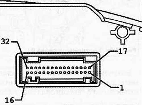
Fig. 7.75. Connector, 32-pin, blue:
1 - terminal 15, plus; 2 - terminal 15, plus; 3 - output signal 1 electronic speedometer; 4 - fuel level sensor 2; 5 - fuel level sensor 1; 6 - indication of insufficient fluid in the windshield washer reservoir; 7 - terminal 31, sensor ground; 8 - terminal 30; 9 - terminal 31, ground; 10 - oil pressure sensor; 11 - outside temperature indication; 12 - Generator indicator lamp, terminal 61; 13-17 - not involved; 18 - terminal 30 S; 19 - terminal 30 S; 20 - not used; 21 - not used; 22 - indication of insufficient amount of coolant; 23 - terminal 30, plus; 24 - terminal 31, ground; 25 - self-diagnosis/wire K; 26-28 - not involved; 29 - warning signal contact for the entire brake system; 30 - not used; 31 - warning light for unfastened seat belts; 32 - not used.
Connector, 32-pin, green
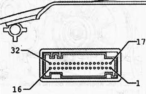
Fig. 7.76. Connector, 32-pin, green:
1-6 - not used; 7 - wear of brake pads; 8 - CAN-out bus, High; 9 - CAN-out bus, Low; 10-12 - not involved; 13 - Parking brake; 14-17 - not involved; 18 - Oil temperature and level warning signal; 19 - CAN bus drive, High; 20 - CAN bus drive, Low; 21-26 - not involved; 27 - CAN bus comfort, High; 28 - CAN bus comfort, Low; 29 - not used; 30 - emergency mode; 31 - CAN bus Infotainment High; 32 - CAN bus Infotainment Low.
Visitor comments