
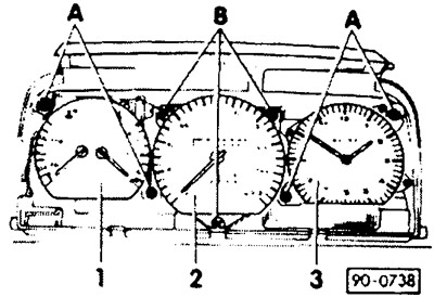
Note: The figure shows the instrument panel with analog clock
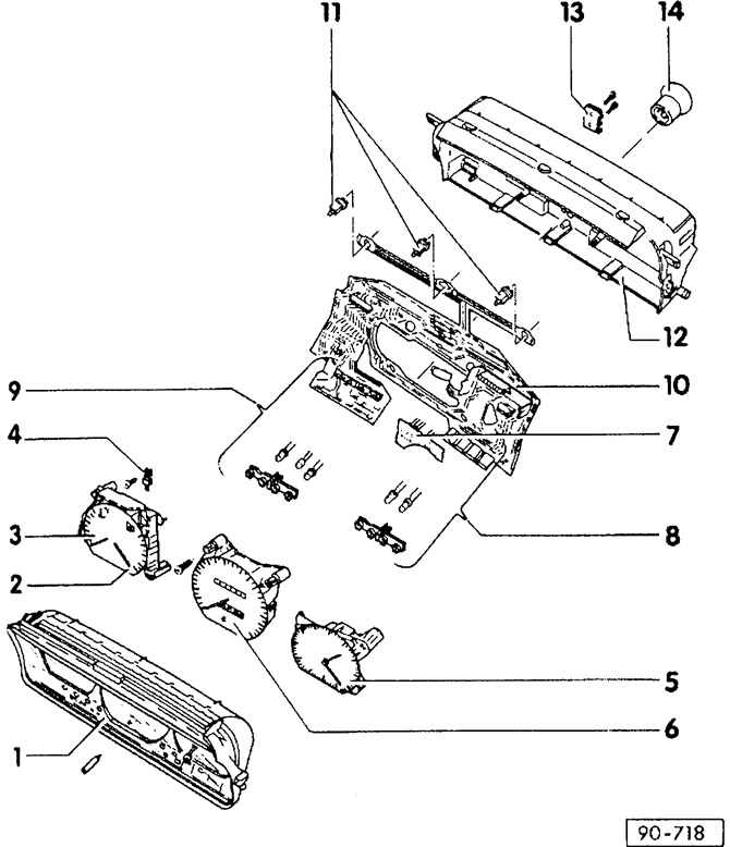
- 1 - protective glass
- 2 - fuel gauge
- 3 - indicating device
For temperature and low coolant level.
- 4 - voltage regulator
- 5 - analog clock
- 6 - speedometer
- 7 - control unit
To control oil pressure.
- 8 - block of signaling devices, right
- 9 - block signaling devices left
- 10 - printed circuit board
- 11 - incandescent lamps
With cartridge, for lighting the instrument panel; 12V, 1.2W.
- 12 - body
- 13 - contact plate
For Hall sensor or inductive sensor. A Hall sensor or an inductive sensor generates a speed signal for various accessories. On vehicles with a universal indicating instrument (MFA) and speed control system (GRA), and/or radio with volume control depending on the speed (GALA), Hall sensor installed. The inductive sensor is applied on vehicles without MFA with GRA and/or GALA. The corresponding sensor is screwed to the back of the speedometer. Contact with the printed circuit board is carried out using the contact spring of the sensor.
- 14 - cover
For speedometer drive shaft.
Note: The figure shows a panel with a universal indicating instrument and a tachometer, with 8/90.
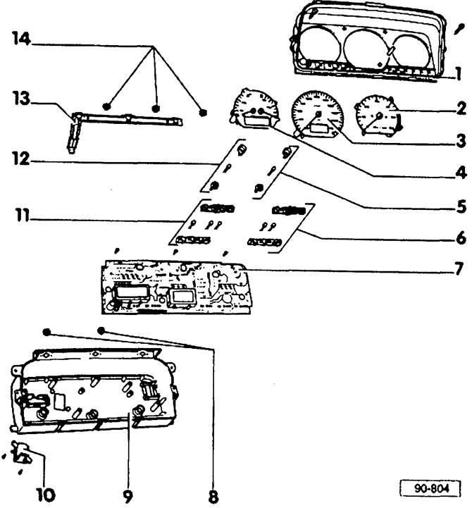
- 1 - protective glass
- 2 - tachometer
- 3 - electronic speedometer
- 4 - indicating instrument
For coolant temperature and fuel capacity with cut-out for universal display (MFA).
- 5 - signaling device
For right turn signal light.
- 6 - block of signaling devices, right
- 7 - board of conductors
Replace only with housing.
- 8 - incandescent lamps
With black socket, for illuminating the universal display and trip odometer.
- 9 - body
Replace only together with conductor board.
- 10 - pressure sensor
For MFA.
- 11 - block signaling devices left
- 12 - signaling device
For left turn signal light.
- 13 - printed circuit board
To illuminate the instrument panel.
- 14 - incandescent lamps
With blue socket for instrument panel lighting: 12V, 1.2W.
Removing
Attention: All parts of the instrument panel, except for the printed circuit board, can be removed separately without dismantling the housing. Operations that only need to be carried out when removing the housing as a set are marked with a ■.
Disconnect ground wire (-) battery.
Remove steering wheel, see chapter «Steering».
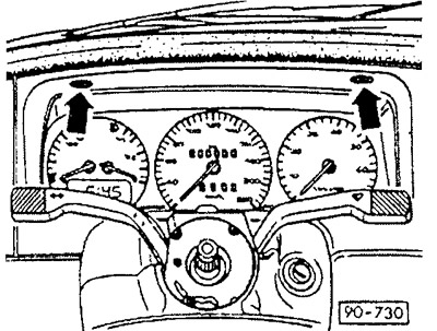
Unscrew the bezel (arrows) and pull it out of the instrument panel.
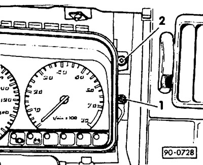
Release screws on left and right -1-.
Unfasten the instrument panel and pull it out on the right side.
Disconnect the plug connector on the back of the housing.
Disconnect hose to pressure sensor for MFA.
Loosen screws -1- for protective glass.
Unscrew the reset knob of the trip meter and remove the protective glass from the instrument panel.
Pull out the instrument panel.
Attention: The tachometer shaft is only inserted.
Removing appliances
Up to 7/90:
Since 8/90:
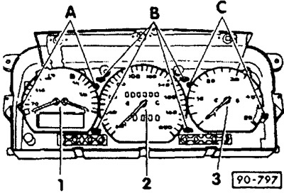
Pull out the fuel gauge and the temperature and low coolant level gauges -1- (depending on version together with digital clock or MFA). Pre-compress locking pins -A-.
After squeezing the locking pins -A-, pull out the analog clock -3- or the tachometer.
Unscrew the mechanical speedometer at points -B- and pull it out (electronic speedometer just inserted).
Removing the oil pressure control unit
The control unit is located on the wiring board behind the analog clock. On vehicles with a tachometer, it is built into the tachometer.
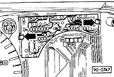
Carefully press the locking tabs in the direction of the arrows and pull the conductor board out of the multi-pin connector on the PCB.
Removing the Voltage Stabilizer
The voltage stabilizer maintains a constant operating voltage supplied to the indicating instruments. It is located in the housing for fuel, temperature and low coolant gauges.
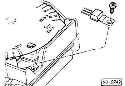
Unscrew the Phillips head screw and remove the voltage stabilizer.
Installation
Insert the voltage stabilizer with three pins into the provided socket and fasten with a cross-slot screw on the head.
Attention: The heat is removed from the voltage stabilizer through the metal reverse side, which for this reason must fit snugly against the substrate.
Plug the control unit for oil pressure monitoring into the multi-pin connector, press in and secure.
Insert the instruments and secure or screw them on.
Attention: The plugs on the reverse side must be inserted into the plug sockets on the printed circuit board during installation.
Connect vacuum hose and multi-pin connector for MFA.
Insert the instrument panel, put it on the tachometer shaft and screw it on. If necessary, remove the footwell cover on the left and, when installing the instrument panel, insert the tachometer shaft from below.
Install protective glass and screw on.
Insert the rim into the lower clamps and screw on at the top.
Check the operation of the instrument panel.
Install steering wheel, see chapter «Steering».
Visitor comments