
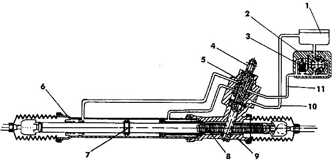
Pic. 391. Section of the steering gear with hydraulic booster: 1 - tank; 2 - hydraulic booster pump; 3 - control valve; 4 - shaft with gear; 5 - valve body; 6 - steering gear housing; 7 - piston; 8 - rail; 9 - crankcase; 10 - drain pipeline; 11 - pressure pipeline
Disconnect the pressure hose from the pump and drain the fluid.
Turn away nuts of both tips of steering draughts, disconnect their pins from the lever of rotary fists with a puller.
Remove the steering gear housing clamp.
Disconnect the intermediate shaft from the steering mechanism by unscrewing both bolts. To remove the shaft, slide it all the way up and then down.
Raise the power unit in an accessible way and unscrew the left bolt from the subframe. Just loosen the right bolt.
Raise the power unit so that the steering gear can be removed from below.
The steering gear is installed in the reverse order. The bolts securing the mechanism to the subframe are tightened with a torque of 130 Nm. Self-locking nuts (necessarily new) are tightened on the tips of the ball pins with a torque of 35 Nm. After installing the steering mechanism, it is filled with working fluid and air is removed, as described here.
Visitor comments