



Caution: If mechanical defects of the turbocharger are detected, for example, the destruction of the pump section wheel, it is not enough to simply replace the turbocharger. To avoid subsequent damage, after carrying out repair work it is necessary to: Check the air filter housing, filter element and air intake hoses for contamination. Check for foreign bodies in the intake tract and intercooler. If found, remove them from the intake tract, replace the intercooler if necessary.
Remove the air filter housing. Remove the sound insulation. Remove the front part of the right fender liner or the front right fender liner. Drain the coolant. Remove the engine skin*. Disconnect the plugs from the ignition coils and move the wiring harness to the 8 side.
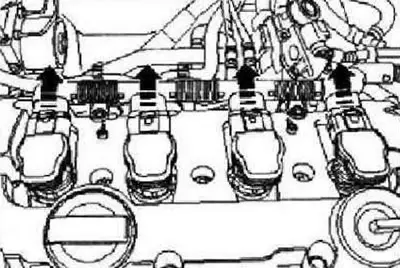
Disconnect the coolant line to the coolant expansion tank "arrow".
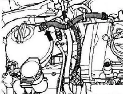
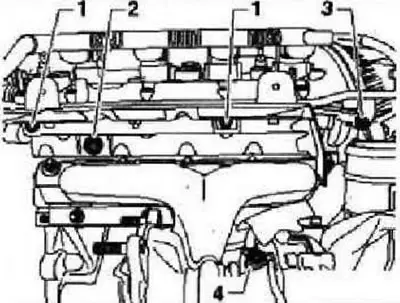
Disconnect the vacuum line "1" at the point of disconnection "2" and release the line. Remove the coolant hoses "arrows" from the cooling system pipe. Unscrew the ground wire "3" and loosen the bolt "4".
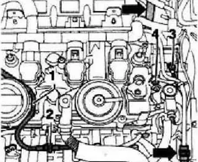
CAWA, CAWB
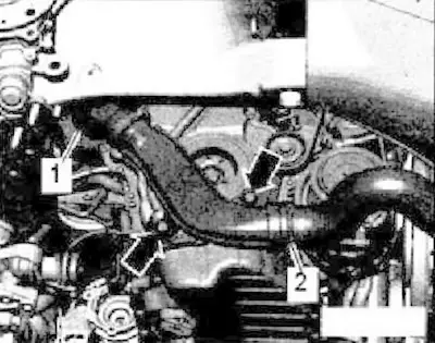
Press the clamps, remove the air duct hose "1" and move it to the side. Unscrew the bolt "arrow" of the air duct pipe. Remove the air duct pipe, loosening the hose clamp "2" for this.
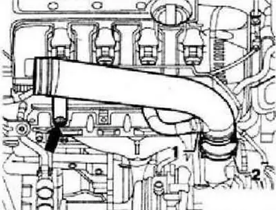
CCTA, CCTB
Unscrew the bolt "arrow" of the air duct pipe. Disconnect the hose clamp "2" and place the air duct pipe on the cylinder head.
All
Close the turbocharger with the plug from the engine kit -VAS 6122-. Unscrew the bolts -1...3- and remove the heat shield together with the coolant pipe.
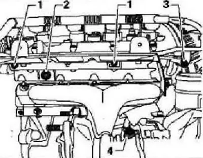
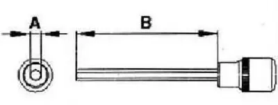
Instructions: Unscrew the bolt "2" of the heat shield using a 6 mm hexagonal socket -A. The hexagonal shape must be at least 5 cm long "B". The socket, which tapers to 6 mm at the end, is thicker.
Unscrew the oil supply line "4" from the turbocharger.
Unscrew the "arrow" bolts. Remove the air duct, for this lift the brackets -1 and 2-.
All-wheel drive vehicles
Remove the heat shield above the right drive shaft.
The information is posted on this resource VWManual
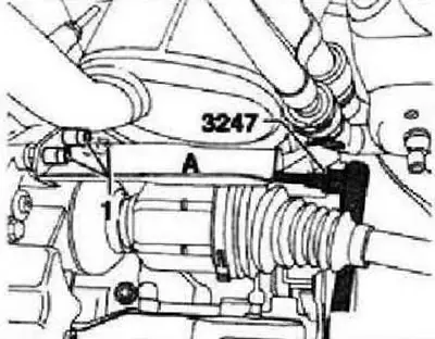
Front wheel drive cars
Unscrew the heat shield of the right drive shaft "arrow".
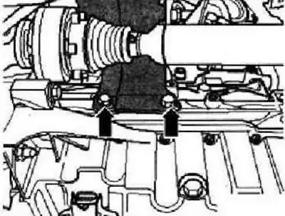
All
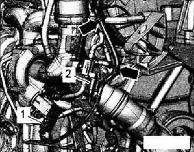
Remove the intake pipe with catalytic converters. Disconnect electrical connectors -1 and 2- and release the "arrow" electrical wire.
Cars with independent heating
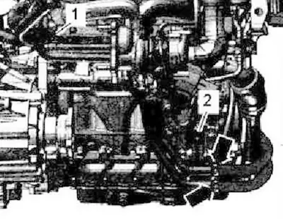
Unscrew screws -1 and 2- and turn the coolant supply pipes to the left.
All
Unscrew bolt "1" using the XZN 10 "T10154" attachment. Unscrew bolt "2".
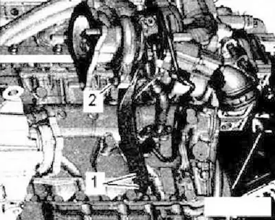
Unscrew the hollow screw "2" and move the coolant lines to the side.
Front wheel drive cars
Unscrew screws "1" securing the oil drain line.
All-wheel drive vehicles
Unscrew the oil drain line from the engine crankcase.
All
Unscrew screw "3" securing the oil supply line.
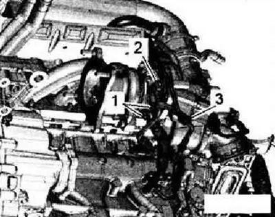
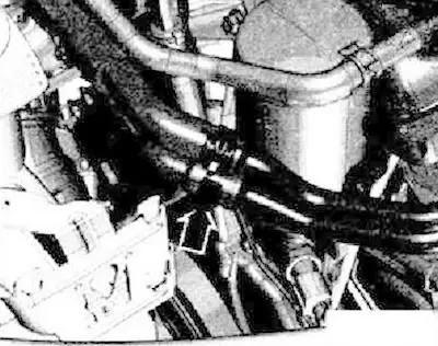
Disconnect and release the coolant hose "arrow".
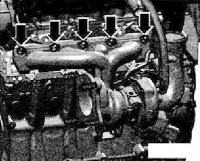
Unscrew the nuts "arrows". Remove the turbocharger / exhaust manifold in an upward direction.
Installation
Caution: If mechanical defects of the turbocharger are detected, for example, the destruction of the pump section wheel, it is not enough to simply replace the turbocharger. To avoid subsequent damage, after carrying out repair work it is necessary to: Check the air filter housing, filter element and air intake hoses for contamination. Check for foreign bodies in the intake tract and intercooler. If found, remove them from the intake tract, replace the intercooler if necessary.
Installation is carried out in the reverse order, observing the following. Gaskets, lip seals and self-locking nuts must be replaced. Fill the turbocharger with engine oil through the connecting pipe for the oil supply line. After installing the turbocharger, let the engine idle for about 1 minute without increasing the speed to ensure proper oil supply to the turbocharger. The coolant return line must be installed together with the turbocharger. Degrease the hose connection pipes and turbocharging system hoses before installation. Only at the union connections should the lip seal and sealing surfaces be lightly greased with oil. Use clamps of the appropriate series to secure all hose connections.
Tightening torque
| Exhaust manifold/turbocharger to cylinder head 1)2) | observe the required tightening sequence |
| Oil feed line to turbocharger | 20 Nm + 45° |
| Return oil line to turbocharger | 9 Nm |
| Coolant supply line to turbocharger | 20 Nm + 45° |
| Turbocharger bracket to cylinder block 2) | 30 Nm |
| Turbocharger bracket to turbocharger 2) | 30 Nm |
| Charge air pipe on the right to the oil pan | 10 Nm |
| Heat shield for cylinder head M8 and M12 | 20 Nm |
1) Replace the nuts.
2) Use heat-resistant grease.
Visitor comments