
Caution: Always tighten the screw clamps on the charge air lines to 5.5 Nm. A low or too high tightening torque can cause the charge air hose to break off the charge air pipe while driving.
Intercooler
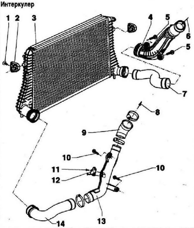
- 1 - 5 Nm
- 2 - Support for intercooler
- 3 - Intercooler
- 4 - Charge air pipe
- 5 - 10 Nm
- 6 - From the turbocharger
- 7 - Charge air hose
- 8 - To air damper unit -J338-
- 9 - Charge air hose
- 10 - 10 Nm
- 11 - 5 Nm
- 12 - Charge pressure sender -G31-
- 13 - Charge air pipe
- 14 - Charge air supply hose
Pressurization system
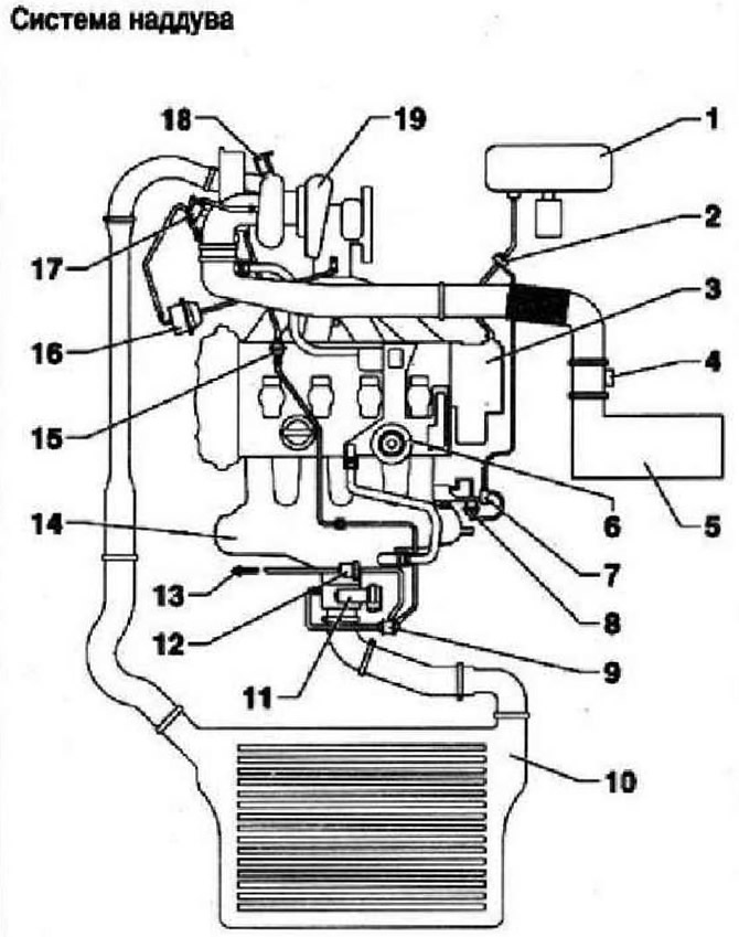
- 1 - Brake booster
- 2 - Check valve
- 3 - Vacuum pump
- 4 - Air mass meter -G70-
- 5 - Air filter
- 6 - Reducing valve of the crankcase ventilation system
- 7 - Intake manifold sequence valve -N156-
- 8 - Vacuum reservoir for changing the geometry of the intake manifold
- 9 - Double safety valve
- 10 - Intercooler
- 11 - Air flap unit -J338-
- 12 - Solenoid valve 1 for activated charcoal filter -N80-
- 13 - To the absorber
- 14 - Intake manifold
- 15 - Check valve
- 16 - Vacuum boost control unit
- 17 - Solenoid valve for boost pressure control N75-
- 18 - Turbocharger relief valve -N249-
- 19 - Turbocharger
Removal and installation of the intercooler
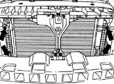
Remove radiator. Remove bumper cover. Remove securing bolts -arrows- and remove intercooler downwards.
Install in reverse order, paying attention to the following. Degrease hose connections and charge system hoses before installation. Only the lip seals and sealing surfaces should be lightly oiled for nipple connections.
Visitor comments