
General instructions for self-diagnosis
The engine control unit is equipped with a self-diagnosis function. Before repair, and also for troubleshooting, the fault memory should first be interrogated. Vacuum hoses and connections should also be checked (air leak through non-density). Fuel hoses may only be secured in the engine compartment with spring clips. The use of clamp or screw clamps is not permitted. A voltage of at least 11.5 V is required for electrical components to operate without failure. Do not use silicone sealant. The silicone mass particles sucked into the engine do not burn out and cause the lambda probes to fail. The vehicle is equipped with a fuel cut-off system in the event of a collision. Turning off (through the corresponding relay) fuel pump, it reduces the chance of a car catching fire after a collision. In addition, this system allows you to reduce the time required to start the engine, thereby increasing the convenience of using the car. When the door is opened, the fuel pump is turned on for 2 seconds, which allows you to pre-create the necessary working pressure in the fuel system, to comply with safety measures.
Units and parts from A to E are not shown in the exploded view.
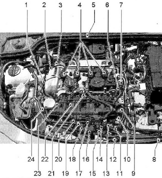
- 1 - Valve 1 for variable valve timing -N205-
- 2 - Charge pressure control solenoid valve -N75- integrated in turbocharger
- 3 - Turbocharger wastegate -N249- integrated in turbocharger
- 4 - Ignition coils with power output stages. Ignition coil 1 with output stage -N70-. Ignition coil 2 with output stage -N127-. Ignition coil 3 with output stage -N291-. Ignition coil 4 with output stage -N292-. Ignition coils are removed from cylinder head with puller -T40039-
- 5 - Engine control unit -J623-
- 6 - Mechanical 1 - high pressure piston pump with fuel pressure control valve -N276-
- 7 - Fuel pressure regulator -N276-
- 8 - Coolant temperature sender at radiator outlet -G83-, in coolant hose
- 9 - Vacuum reservoir for charge air control dampers
- 10 - Intake manifold flap valve -N316-
- 11 - Engine speed sender -G28-, fitting location - bottom front left
- 12 - Charge pressure sender -G31-
- 13 - Connector for knock sensor 1 -G61-, installation location under intake manifold. Knock sensor 1 -G61-, 20 Nm
- 14 - Electrical connector for Hall sender -G40-, installation location under intake manifold
- 15 - 8-pin connector for injectors, installation location - under the intake manifold
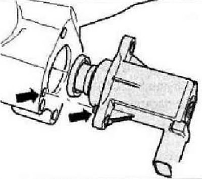
- 16 - Choke valve unit -J338- with throttle valve actuator -G186-, throttle valve actuator angle sender 1 -G187- and throttle valve actuator angle sender 2 -G188-. After replacing the throttle valve unit -J338-, adapt it again to the engine control unit -J623-, tester -VAS 5051B-
- 17 - Solenoid valve 1 for activated charcoal filter -N80-
- 18 - Intake air temperature sender -G42-, bolted to intake manifold
- 19 - Knock sensor 1 -G61-, on the cylinder block at the front under the intake manifold, 20 Nm
- 20 - Coolant temperature sender -G62-, in coolant pump housing
- 21 - Hall sender -G40-, bolted to cylinder head cover at front
- 22 - Fuel pressure sender -G247-, on fuel rail (Rail)
- 23 - Intake manifold flap potentiometer -G336-, right in intake manifold
- 24 - Oil pressure sender -F1-, in accessory bracket
- A - Diagnostic connector, in the driver's footwell
- B - Air mass meter -G70- and intake air temperature sender 2 -G299-
- C - Accelerator pedal position sender -G79- and accelerator pedal position sender 2 -G185-, on the accelerator pedal (both sensors are installed in a single housing), when replacing the accelerator pedal module or engine control unit in vehicles with automatic transmission, the kick-down function must be set
- D - Radiator fan control unit -J293-, radiator fan control unit -J293- integrated in radiator fan -V7-
- E - Injectors, in the fuel rail (Rail), cylinder 1 injector -N30-, cylinder 2 injector -N31-, cylinder 3 injector -N32-, cylinder 4 injector -N33-
Technical data
| Engine codes | CAWA, CAWB, CSTA, CCTB |
| Idling. Idling speed, rpm 1) | 640...800 |
| Speed limitation, rpm | approximately 6500 |
1) When the supply voltage of the engine control unit drops below 12 V, the idling speed gradually increases to 990 / min. The idle speed is not adjustable.
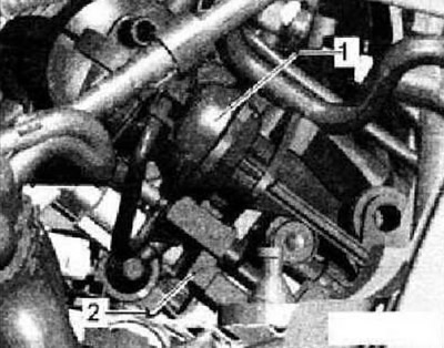
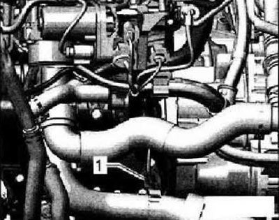
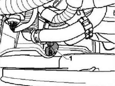
High pressure pump
- 1 - High pressure fuel pump (injection pump)
- 2 - Fuel pressure regulator -N276-
Intake manifold flap valve -N316-2-
1 - Vacuum reservoir for charge air control flaps
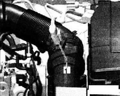
Air mass meter -G70- and intake air temperature sender 2 -G299-1-
Engine speed sender -G29-1-
Hall sender -G40-1-
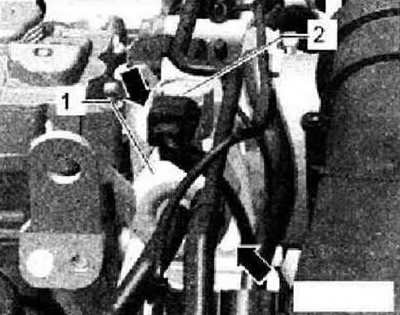
Electrical connectors
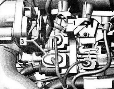
- 1 - Hall sender -G40-
- 2 - Knock sensor 1-G61-
- 3 - 8-pin connector for injectors
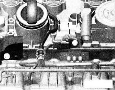
Coolant temperature sender -G62-1-
Instruction: Under intake manifold (the collector is missing in the picture).
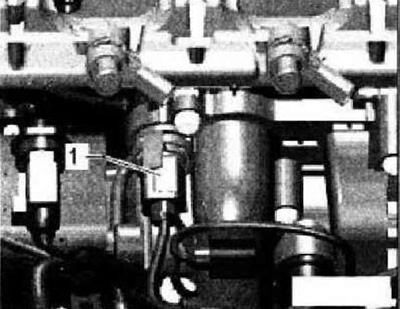
Charge pressure sender -G31-1-
Turbocharger components
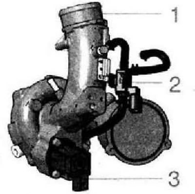
- 1 - Removal and installation of the turbocharger
- 2 - Tighten charge pressure control solenoid valve -N75- to 3 Nm
- 3 - Tighten turbocharger relief valve -N249- to 7 Nm (observe installation position, following figure)
Note installation position of turbocharger wastegate -N249-
Visitor comments