
Instruction; Follow safety rules™. Follow the rules for maintaining cleanliness. To access the injector» the intake manifold and the fuel rail with charge air control flaps must be dismantled. The Teflon O-ring of the combustion chamber and the O-ring must be replaced.
WARNING: The fuel system is under pressure!
Only vehicles with resonator: Remove charge air guide pipe to resonator. Remove engine cover. Clean the transition from the intake manifold to the MCC. Remove air filter.
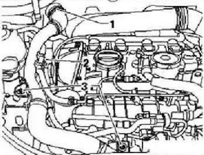
Disconnect vacuum line -arrow- to activated charcoal filter. Disconnect the following electrical connectors: intake air temperature sender -G42-1-, throttle valve unit -J338-2-, activated charcoal filter solenoid valve 1 -N80-, hall sender -G40-.

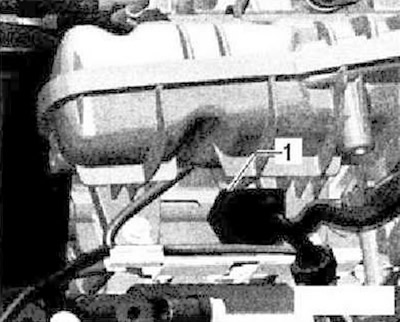
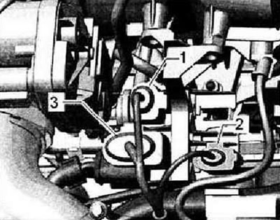
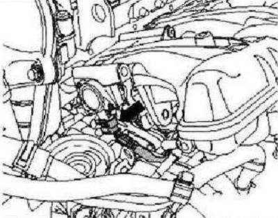
Detach vacuum line -1- at disconnection point -2- and remove crankcase breather hose -3-.

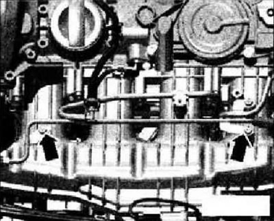
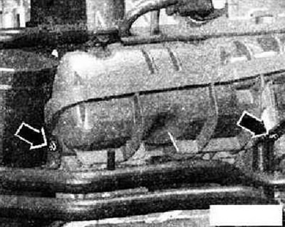
Unscrew bolts -arrows- for fuel supply line and move it to one side.
Instructions: Relieve pressure in the fuel system.
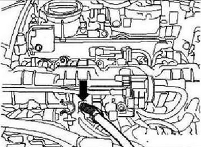
Unscrew union nut for fuel line -lower arrow-.
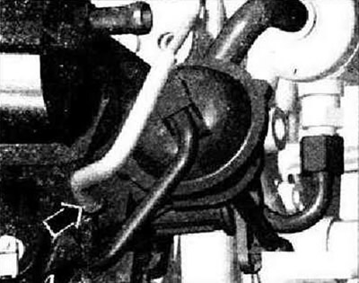
Detach vacuum line -arrow- from intake manifold flap valve -N316-.
Unscrew bolts -arrows- for 0g lines from intake manifold.
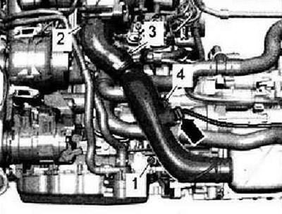
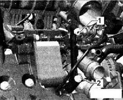
Disconnect electrical connector -1- from fuel pressure sender -G247-.
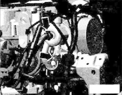
Detach hose clamp -2-. Remove bolt -4-. Unplug electrical connector -arrow-. Remove soundproofing.
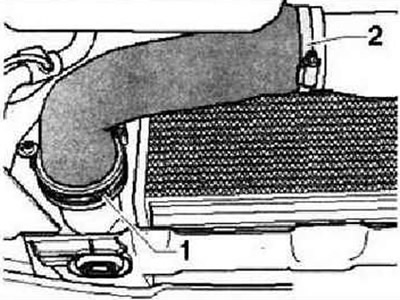
Remove air duct -1 and 2-.
Remove bolt -1- and remove air duct downwards. Unplug electrical connectors -1...3- and unscrew bracket from intake manifold.
Remove support for intake manifold, to do this unscrew securing nut -1- and screw -2-. Remove oil filter.
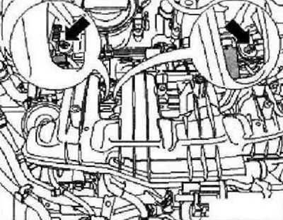
Detach cable retainer -arrows-.

Disconnect cable -arrow- from intake manifold.
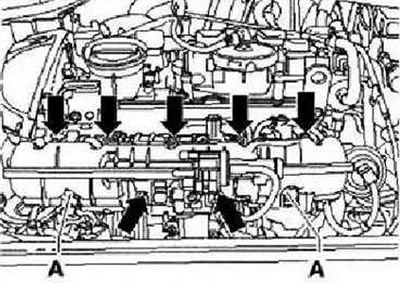
Unscrew nuts -A- and bolts -arrows- with socket -T10347- from intake manifold. Carefully lift the intake manifold slightly off the main cylinder head rail.
Disconnect electrical connector -arrow- from intake manifold flap potentiometer -G336- and remove intake manifold. Plug inlet passages with clean rags.
Instruction: The injectors may remain inserted into the fuel rail.
Remove the fuel rail from the intake manifold.
Installation
The nozzles are inserted into the MCC. Fit the intake manifold through the dowel pins (left and right bottom) at GVC.
Note: Pay attention to the correct installation position of the injectors and when pushing the intake manifold onto the cable holder (under the intake manifold).
When carrying out assembly work on the intake manifold, the intake manifold must be removed slightly again while leaving the injectors inserted in the fuel rail. Then remove the injectors from the fuel rail again and insert them into the main cylinder head. Further installation is carried out, respectively, in the reverse order of removal. In doing so, the following must be observed. When fixing the cable fastener to the intake manifold, also fasten the other two fasteners.
Visitor comments