
English Русский
Български
Беларускі
Український
Српски
Hrvatski
Română
Polski
Slovenský
Magyar
  |  Articles  |  Sitemap  |  Contacts  |    |
Car maintenance Ford Car maintenance Hyundai Car maintenance Chevrolet Car maintenance BMW Car maintenance Audi Car maintenance Opel Car maintenance AvtoVAZ
VWmanual.ru


Main   Passat   Golf   Polo   Touareg   Tiguan   Sharan   Transporter   Others  
Polo 3 (1995-2003) Polo 4 (2001-2009)

Intake manifold/fuel manifold/valve injectors (VW Polo 4)

  • Main
  • Polo
  • Polo 4
  • Power unit
  • Control system
  • Intake manifold/fuel manifold/valve injectors
            0


Petrol engine with a working volume of 1.2 liters
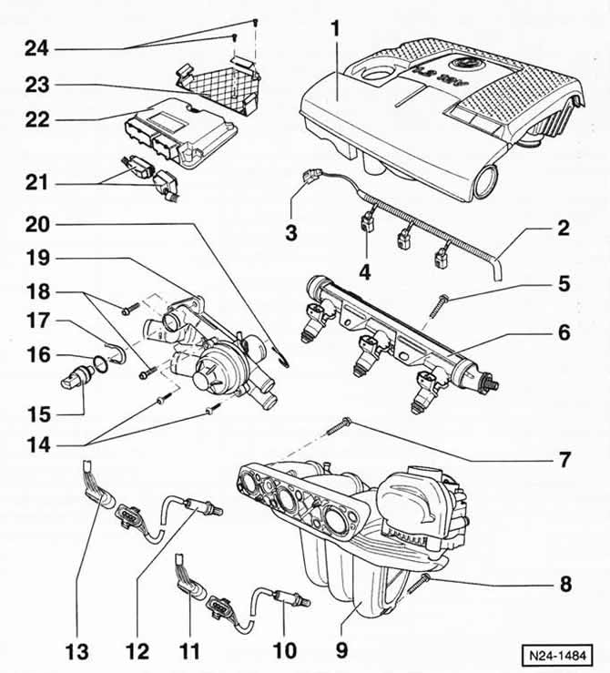


1 - Upper engine cover

1 - Upper engine cover
With built-in air filter.

2 - wire guide

3 - connecting plug

For crankshaft speed sensor, black, 2-pin.

4 - connecting plug
For valve injector, black, 2-pin.

5 — bolt, 10 Nm

6 - fuel manifold with injectors

7 — bolt, 20 Nm

8 — bolt, 20 Nm

9 — intake manifold

10 — oxygen sensor 1, 50 Nm

Installed before the catalytic converter. Apply VW-G 052 112 AZ lubricant to the threads before installation.

Caution: Do not allow grease to come into contact with the splines of the sensor housing.


11 — plug connector
For oxygen sensor 1 (before the catalytic converter), heated, 6-pin, black, pins 3 and 4 gold plated.

12 — oxygen sensor 2, 50 Nm
Installed after the catalytic converter. Apply VW-G5 grease to the threads before installation. Caution: Do not allow grease to get on the splines of the sensor housing.

13 — plug connector
For oxygen sensor 2 (after the catalytic converter), 4-pin, black.

14 - bolts, 10 Nm

15 - coolant temperature sensor

For engine control unit, with sensor for coolant temperature gauge. Connection color: green. Before removing, if necessary, relieve pressure in the cooling system.

16 — sealing ring
Replace if damaged.

17 — clamp
Check the reliability of the fastening.

18 - bolts, 10 Nm

19 — thermostat housing

20 — clamp

Check the reliability of the fastening.

21 - Connecting plugs

Caution: Only disconnect and connect the plug connectors when the ignition is switched off.


22 — Engine control unit
When replacing the control unit, it must be coordinated with the anti-theft system.

23 — Engine control unit holder

24 - screws, 5 Nm
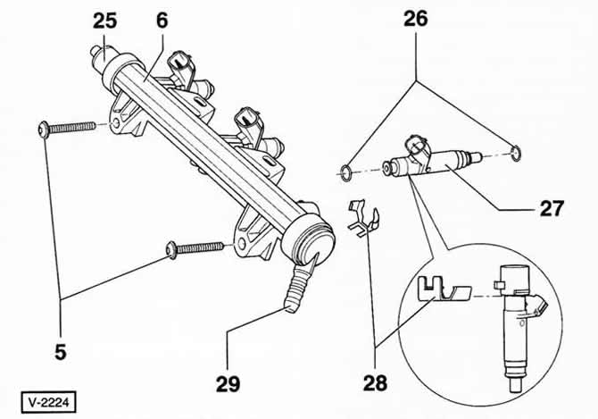

25 — air bleed nipple

25 — air bleed nipple

26 - sealing rings

Always replace. Lubricate with fresh engine oil before installation.

27 — nozzle

28 - clamps

29 — fuel supply nipple

Black with white markings.

Note: Figure V-2224 shows the 1.2L AZQ engine components supplied with 12 volts.

This article is available at russian, bulgarian, belarusian, ukrainian, serbian, croatian, romanian, polish, slovak, hungarian
The text has been checked: Semenova Anna

Share information:

Previous articles
General inspection of the injection system
Checking/adjusting idle speed/ignition timing/CO content
Sensors and actuators of injection systems
Operation of the gasoline engine management system
Safety precautions when working with the injection system of a gasoline engine
Gasoline injection and ignition system
Next articles
Technical characteristics of injection systems for gasoline engines
Diagnostics of malfunctions of injection systems of gasoline engines
Ignition system
Ignition coils/spark plugs


Similar articles from other manuals for VW cars:
Checking the intake manifold heating system Passat B3 (1988-1993)
Overload cut-off valve and intake manifold heater (1.8 models… Golf 2 (1984-1993, petrol)
Removal and installation the intake manifold (diesel engine) Touareg 1 (2002-2006)
Removal and installation the intake manifold with fuel rail Tiguan 1 (2007-2015)
Removal and installation the exhaust manifold Sharan 1 (1995-2000)
Checking and replacing the intake manifold heater Transporter T3 (1979-1992)
Fuel manifold parts with injectors Caddy 3 (2003-2010)
Link to this page in different formats


Visitor comments


No comments yet


How much will 27 + 45 =


Polo 4 
  • General information
  • User manual
  • Maintenance
  • Power unit
  • Engine repair
  • Cooling and lubrication system
  • Control system
  • Injection system (diesel)
  • Supply system
  • Exhaust system
  • Chassis
  • Front suspension
  • Rear suspension
  • Steering
  • Wheels and tires
  • Brake system
  • Body
  • Interior
  • Exterior
  • Electrical equipment
  • Equipment and devices
  • Wiper system
  • Lighting system
  • Electrical circuits
Polo 3 
  • General information
  • User manual
  • Maintenance
  • Power unit
  • Petrol engines 1.4 and 1.6
  • Petrol engines 1.4 (V16)
  • Petrol engines 1.6 and 1.8
  • Diesel engines 1.7 and 1.9
  • Diesel engines 1.9 D and TD
  • Transmission
  • Mechanical gearbox 085
  • Mechanical gearbox 020/02K
  • Chassis
  • Front suspension
  • Rear suspension
  • Steering
  • Brake system
  • Body
  • Exterior
  • Interior
  • Electrical equipment
  • Equipment and instruments (until 2000)
  • Equipment and instruments (after 2000)
  • Electrical circuits
  • Wiring diagrams (petrol)
  • Wiring diagrams (diesel)
VWmanual.ru © 2016-2026 | Mobile version | News and articles | Sitemap: EN BG BY UA RS HR RO PL SK HU | Write message | Site search
Passat B2 • Passat B3 • Passat B4 • Passat B5 • Passat B6 • Golf 1, diesel • Golf 1, petrol • Golf 2, petrol • Golf 2 • Golf 3 • Golf 4 • Golf 5 • Polo 3 • Polo 4 • Touareg 1 • Tiguan 1 • Sharan 1 • Transporter T3 • Transporter T4 • LT 28 • LT 2D • Beetle • Caddy 3 •
Our website uses cookies to ensure functionality and convenience.