
Removal and installation of the fuel supply module
Caution: Condition: The fuel tank must not be more than 1/2 full. This ensures that the fuel level is below the fuel delivery module flange.
Instruction. When replacing the fuel delivery module, check the fuel tank for coarse dirt and clean if necessary. Empty the fuel tank using the fuel extractor -VAS 5190-. Strictly observe the safety regulations. Follow the rules for maintaining cleanliness.
Remove the rear bench seat. Remove the cover from the fuel delivery module.
ATTENTION: The fuel in the power supply system is under pressure!
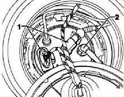
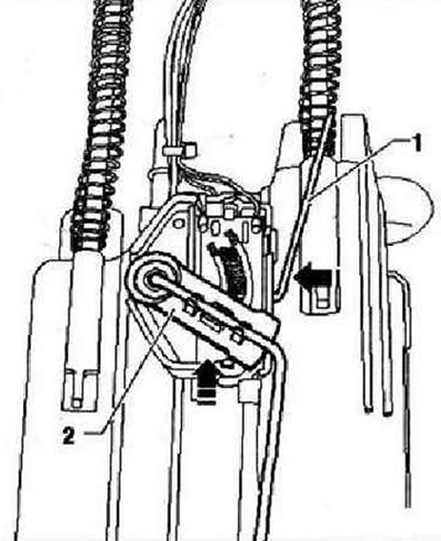
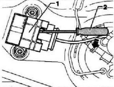
Disconnect connector -1- and fuel line -2- from right (in the direction of travel) flange.
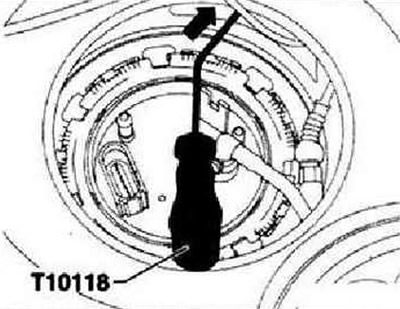
Release connector -arrow- on fuel pump control unit -J538- with tool -T10118- and unplug connector.
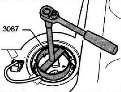
Unscrew round nut using fuel gauge spanner -3087-. Lift the fuel delivery module slightly and remove the O-ring from the fuel tank opening.
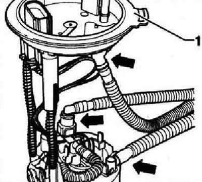
Unlock and disconnect fuel lines at fuel delivery unit -arrows- and remove fuel delivery unit from fuel tank.
Installation of the fuel pump is carried out in the reverse order.
Instruction: The fuel lines must be properly secured -arrows- (hoses match fittings). Check that the male connectors are firmly seated by pulling on them! When installing the fuel delivery unit, take care not to bend the float lever of the fuel gauge sender -G-. Install the sealing ring of the fuel supply module dry into the hole in the fuel tank. Moisten O-ring with fuel (only when fuel delivery module is installed). Pay attention to the installation position of the flange of the fuel delivery unit: the lug -1- points in the direction of travel. The fuel delivery module flange can only be installed in this position.
Removing and installing fuel level sensor G
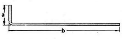
Remove the fuel delivery module. Bend the 80mm welding wire as shown. Dimension -a-: = 10 mm, Dimension -b-: 70 mm.
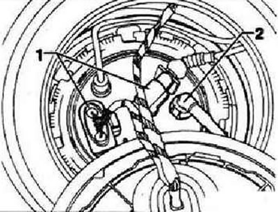
Unlock and remove wiring connector for fuel level sender 2. Push welding wire -1- in direction of arrow- into recess under sender.
At the same time push the fuel level sender -2- in -direction of arrow- out of the guides.
Installation
Insert the fuel level sensor into the guides of the fuel delivery module and push down until it locks into place. Connect the connectors and check that they are securely fixed. Install the fuel delivery module.
Removing and installing fuel pump control unit -J538-
Note: The fitting location for the fuel pump control unit -J538- is on the fuel tank.
Fitting location for fuel pump control unit -J538-
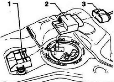
- 1 - Bracket for fuel pump control unit -J538-
- 2 - Fuel pump control unit -J538-
- 3 - Connector
Remove the right, in the direction of travel, casing from the fuel supply module. Disconnect connector -1-.
Insert a screwdriver -2- directly above the connector into the recess in the bracket. Move the screwdriver in the -direction of the arrow-.
Press the screwdriver downwards in -direction of the arrow- and at the same time remove the control unit at the connector from the bracket. Remove the connector from the control unit.

Installation
Plug connector -3- into control unit -2-. Push control unit -2- into bracket -1- until it snaps into place. Further installation is carried out in the reverse order.
Electronic fuel management system (E-Gas system) - accelerator pedal module
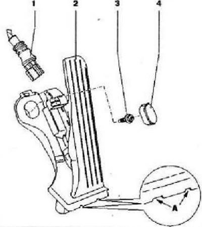
- 1 - Connector, black, 6-pin
- 2 - Accelerator pedal position sender -G79- with accelerator pedal position sender 2 -G185-, not adjustable. The accelerator pedal position sensor transmits to the engine control unit data on the desired engine power, -A- grooves for the puller
- 3 - 10 Nm
- 4 - Cap
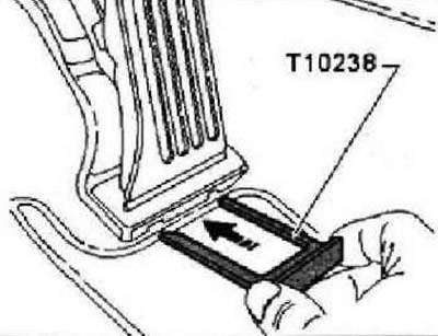
Removing and installing the accelerator pedal module
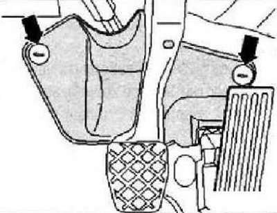
Remove steering column trim -arrows-.
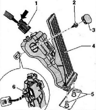
Use a screwdriver to pry off and remove the cover -3-. Remove securing bolt -2-. Unlock connector -1- -arrow- and remove accelerator pedal module.
Insert puller -T10233- as far as it will go into the recesses provided for this purpose and remove the accelerator pedal module.
Installation
Plug connector -1- into accelerator pedal module -4-. Lock connector -arrow-. Fit the accelerator pedal module to the mounting pins -5-. Insert pin -6- into floor hole. Secure accelerator pedal module with bolt -2- and fit cap -3-. Fit steering column trim. Tightening torque: accelerator pedal module to body 10 Nm.
Activated carbon absorber system (CAWA, CAWB)
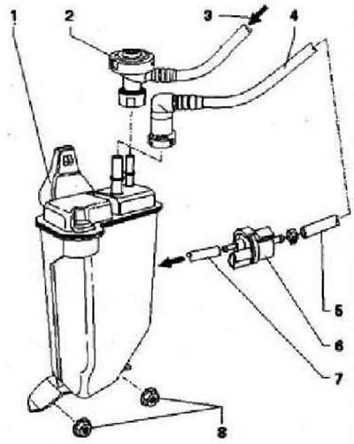
- 1 - Activated charcoal absorber, installation location: in the rear right wheel arch
- 2 - Pressure reducing valve with connecting hose, for dismantling take the pressure reducing valve by the retaining ring (gray) and pull up, check the security of fastening
- 3 - From the fuel tank
- 4 - Ventilation line to solenoid valve 1 for activated charcoal filter -N80-, clipped to fuel tank, check secure fit
- 5 - Ventilation line from the activated carbon absorber, check the security of fastening
- 6 - Activated charcoal filter solenoid valve 1 -N8Q-, when the ignition is off, the valve is closed, when the engine is warm, it is controlled by a simulated signal from the engine control unit
- 7 - Connecting hose to the intake manifold, check the fastening
- 8 - 10 Nm
Visitor comments