
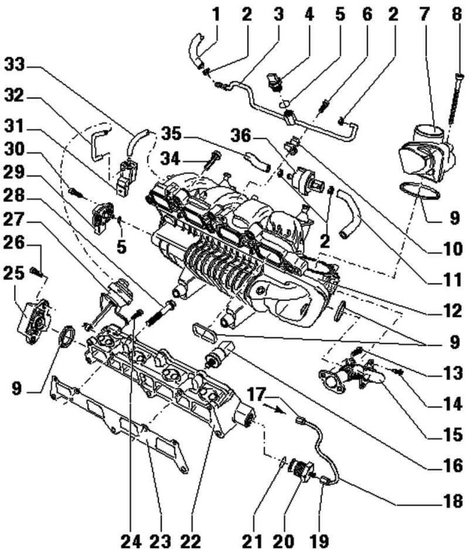
Pic. 2.66. Intake Manifold Components: 1 - supply fuel line; 2 - clamp; 3 - fuel line; 4 - fuel pressure sensor for low pressure 18 Nm; 5 – O-ring; 6 - bolt 10 Nm; 7 - throttle control module; 8 - bolt 10 Nm; 9 - sealing ring; 10 – fixing clip; 11 - from the solenoid valve 1 of the absorber with activated carbon; 12 - intake manifold; 13 - bolt 8 Nm; 14 - bolt 5 Nm; 15 - connecting tube; 16 - fuel pressure sensor 20 Nm; 17 - union nut, 30 Nm; 18 - high pressure line; 19 - union nut, 25 Nm; 20 - bolt 20 Nm; 21 – O-ring; 22 - the lower part of the intake manifold; 23 - gasket; 24 - bolt 10 Nm; 25 - intake manifold flap potentiometer; 26 - bolt 1.5 N·m; 27 - vacuum drive; 28 - bolt 20 Nm; 29 - pressure sensor in the intake manifold; 30 - bolt 5 Nm; 31 - damper valve in the intake manifold; 32 - vacuum hose; 33 - vacuum hose; 34 - bolt 20 Nm; 35 - to the solenoid valve 1 of the absorber with activated carbon; 36 - solenoid valve 1 absorber with activated carbon
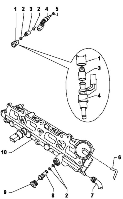
Pic. 2.67. Fuel rail with injectors: 1 - mounting bracket; 2 – O-ring; 3 - spacer sleeve; 4 – nozzle of cylinder 4; 5 - sealing ring; 6 - vacuum hose; 7 - return line; 8 - pressure reducing valve; 9 - bolt 20 Nm; 10 - the lower part of the intake manifold
Checking the functioning of the intake manifold flap
After installing the new lower intake manifold, remove the vacuum actuator mounting bracket.
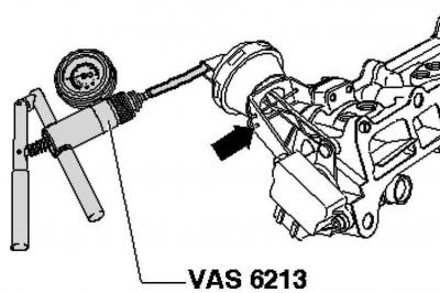
Pic. 2.68. Connecting the hand vacuum pump
Connect the hand vacuum pump as follows (pic. 2.68).
Create a vacuum and check the serviceability of the actuator of the vacuum drive by the arm of the lever.
Note: With the intake manifold removed, the operation of the intake manifold flap can be checked at the same time.
Visitor comments