English Русский
Български
Беларускі
Український
Српски
Hrvatski
Română
Polski
Slovenský
Magyar
  |  Articles  |  Sitemap  |  Contacts  |    |
Car maintenance Ford Car maintenance Hyundai Car maintenance Chevrolet Car maintenance BMW Car maintenance Audi Car maintenance Opel Car maintenance AvtoVAZ
VWmanual.ru


Main   Passat   Golf   Polo   Touareg   Tiguan   Sharan   Transporter   Others  
Tiguan 1 (2007-2015)

Turbocharger device (VW Tiguan 1)

  • Main
  • Tiguan
  • Tiguan 1
  • Power unit
  • Engine 2.0 (petrol)
  • Turbocharger device
            0


Instructions: Use clamps of the appropriate series to secure all hose connections. Degrease hose connection pipes and supercharging system hoses before installation. Only the union connections should be lightly lubricated with oil on the lip seal and sealing surfaces. The supercharging system must be sealed. Self-locking nuts must be replaced. Fill the turbocharger with engine oil through the connecting pipe for the feed oil line. After installing the turbocharger, let the engine run at idle speed (do not increase the speed) for 1 minute to ensure that oil is supplied to the turbocharger. Observe the rules for maintaining cleanliness.

Instructions: Use clamps of the appropriate series to secure all hose connections. Degrease hose…

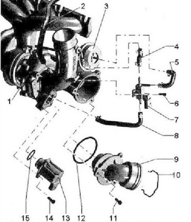
  • 1 - Turbocharger, can only be replaced with the exhaust manifold and vacuum block
  • 2 - To the activated carbon absorber
  • 3 - Turbocharger vacuum block
  • 4 - Hose
  • 5 - Hose
  • 6 - Bolt, 3 Nm
  • 7 - Boost pressure limitation solenoid valve "N75"
  • 8 - Hose
  • 9 - Branch pipe
  • 10 - Locking bracket
  • 11 - Bolt, 9 Nm
  • 12 - O-ring, replace
  • 13 - Turbocharger bypass valve N₂49-, note installation position
  • 14 - Bolt, 7 Nm
  • 15 - O-ring, replace


15 - O-ring, replace

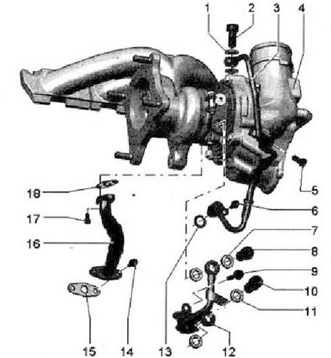
  • 1 - O-ring, replace
  • 2 - Bolt, 20 Nm + turn 45°
  • 3 - Pressure oil line
  • 4 - Turbocharger, can only be replaced with the exhaust manifold and vacuum block
  • 5 - Bolt, 9 Nm
  • 6 - Bolt, 9 Nm
  • 7 - O-ring, replace
  • 8 - Bolt, 20 Nm + 45° further tightening
  • 9 - Bolt, 9 Nm
  • 10 - Bolt, 20 Nm + 45°
  • 11 - O-ring, replace
  • 12 - Cooling system pressure hose
  • 13 - O-ring round section, replace
  • 14 - Bolt, 9 Nm
  • 15 - Gasket, replace
  • 16 - Return oil line
  • 17 - Bolt, 9 Nm
  • 18 - Gasket, replace


18 - Gasket, replace

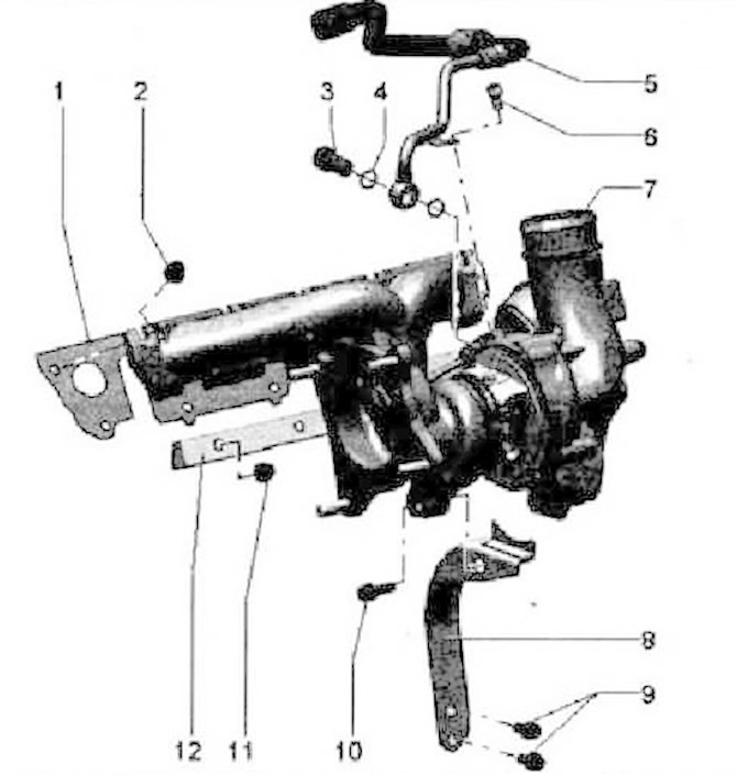
  • 1 - Gasket, replace
  • 2 - Nut, replace. Lubricate the exhaust manifold mounting pins with heat-resistant paste
  • 3 - Bolt, 20 Nm + 45° further tightening
  • 4 - O-ring, replace
  • 5 - Return hose of the cooling system
  • 6 - Bolt, 9 Nm
  • 7 - Turbocharger, can only be replaced with the exhaust manifold and vacuum block
  • 8 - Bracket
  • 9 - Bolt, 30 Nm, lubricate the bolt with heat-resistant paste
  • 10 - Bolt, 30 Nm, lubricate the bolt with heat-resistant paste
  • 11 - Nut, do not unscrew to remove the turbocharger, replace, 30 Nm, lubricate the exhaust manifold mounting pins with heat-resistant paste
  • 12 - Clamping bar


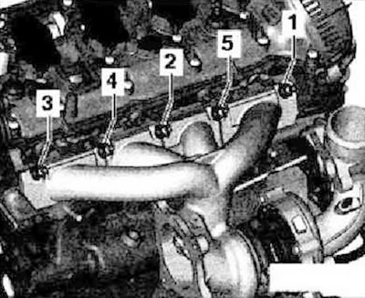
Turbocharger - Bolt Tightening Sequence


The original information is posted on the resource: VWManual


Turbocharger - Bolt Tightening Sequence


Tighten bolts -1-5- in 4 stages.
  • 1. Tighten the bolts to 5 Nm.
  • 2. Tighten the bolts to 12 Nm.
  • 3. Tighten the bolts to 16 Nm.
  • 4. Tighten the bolts to 25 Nm.

Installation position of the turbocharger air bypass valve "N₂49"
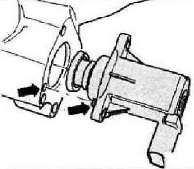


Installation position of the turbocharger air bypass valve «N₂49»


Pay attention to the installation position of the "arrow".

This article is available at russian, bulgarian, belarusian, ukrainian, serbian, croatian, romanian, polish, slovak, hungarian
The text has been checked: Tarasov Ivan

Share information:

Previous articles
Fuel system repair
Removal and installation the fuel tank
Fuel tank device
Pressure relief in high pressure areas (CAWA, CAWB, CCTA, CCTB)
Safety rules for working with the power supply system
Radiator, fan rack and radiator fan
Next articles
Removal and installation a turbocharger
Turbocharging system
Fuel injection system
Air filter device
Intake manifold device
Fuel ramp device (Rail)


Similar articles from other manuals for VW cars:
Constant speed control device Passat B3 (1988-1993)
Cooling system device Golf 2 (1984-1993, petrol)
Device switches Polo 3 (1995-2003)
Checking the turbocharger Touareg 1 (2002-2006)
Diesel engine fuel system and turbocharger Sharan 1 (1995-2000)
Windscreen wiper drive device Transporter T4 (1990-2003)
A device that prevents children from opening a sliding door Caddy 3 (2003-2010)
Link to this page in different formats


Visitor comments


No comments yet


How much will 28 + 46 =


Tiguan 1 
  • General information
  • Characteristics
  • Vehicle overview
  • Power unit
  • Petrol engine 1.4 BWK
  • Petrol engine 1.4 CAVA
  • Engine 2.0 (petrol)
  • Engine 2.0 (diesel)
  • Transmission
  • 6-speed manual gearbox 0A6
  • 6-speed automatic gearbox 09M
  • Drive shafts
  • Chassis
  • Front suspension
  • Rear suspension (2x4)
  • Rear suspension (4x4)
  • Air suspension
  • Wheels and rims
  • Brake system
  • Steering gear
  • Body
  • External equipment
  • Internal equipment
  • Electrical equipment
  • Power devices
  • Appliances and lighting
  • Communication systems
  • Heating and air conditioning
  • Electrical circuits
VWmanual.ru © 2016-2026 | Mobile version | News and articles | Sitemap: EN BG BY UA RS HR RO PL SK HU | Write message | Site search
Passat B2 • Passat B3 • Passat B4 • Passat B5 • Passat B6 • Golf 1, diesel • Golf 1, petrol • Golf 2, petrol • Golf 2 • Golf 3 • Golf 4 • Golf 5 • Polo 3 • Polo 4 • Touareg 1 • Tiguan 1 • Sharan 1 • Transporter T3 • Transporter T4 • LT 28 • LT 2D • Beetle • Caddy 3 •
Our website uses cookies to ensure functionality and convenience.