
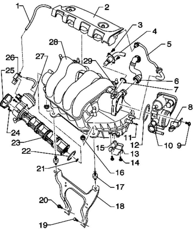
Pic. 2.220. Intake Manifold Components: 1 - vacuum hose; 2 – vacuum receiver; 3 - bolt 10 Nm; 4 - connecting pipe for exhaust gas recirculation; 5 - vacuum hose; 6 – a hose of ventilation of a crankcase of the engine; 7 - sealing ring; 8 - bracket; 9 - bolt 8 Nm; 10 - throttle control module; 11 - connection for the ejection pump; 12 - sealing ring; 13 - pressure sensor in the intake manifold with an intake air temperature sensor; 14 - bolt 3 Nm; 15 – O-ring; 16 - bolt 10 Nm; 17 - rubber-metal support; 18 - intake manifold support; 19 - bolt 25 Nm; 20 - bolt 40 Nm; 21 - sealing ring; 22 - sealing ring; 23 - contact cylinder; 24 - bolt 7 Nm; 25 - cover; 26 - valve for switching the intake manifold register; 27 - vacuum drive; 28 - intake manifold; 29 - connection for the solenoid valve 1 of the absorber
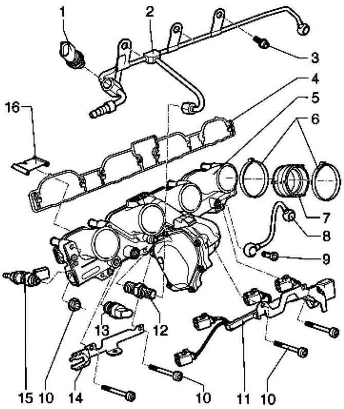
Pic. 2.221. Fuel Rail Components (engine codes BLR, BLX, BLY): 1 - fuel pressure sensor for low pressure; 2 – fuel line; 3 – a bolt with an internal hexagon; 4 - seal; 5 - fuel rail with intake manifold flap motor and intake manifold flap potentiometer; 6 - clamp; 7 - fitting; 8 - fuel line; 9 - bolt 15 Nm; 10 - bolt 10 Nm; 11 - plug; 12 - pressure reducing valve; 13 - fuel pressure sensor; 14 - bracket; 15 - nozzle of cylinder 1 to nozzle of cylinder 4; 16 - partition
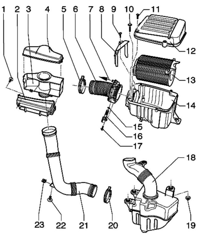
Pic. 2.222. Air filter components: 1 - bolt 5 Nm; 2 - air channel; 3 - air funnel; 4 - valve; 5 - spring clamp; 6 - air intake sleeve; 7 - connection for the ejection pump; 8 - bracket; 9 - bolt 2 Nm; 10 - bolt 8 Nm; 11 - bolt 3 Nm; 12 – the top part of the air filter; 13 - filter insert; 14 - air filter housing; 15 - sealing ring; 16 - intake air temperature sensor 2; 17 - bolt 2 Nm; 18 - expansion tank; 19 - bolt 20 Nm; 20 - spring clamp; 21 - air duct hose; 22 - bolt 2 Nm; 23 - insert nut
Note: Take precautions.
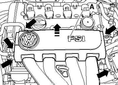
Remove, if present, the engine cover.
Pic. 2.223. Vacuum receiver
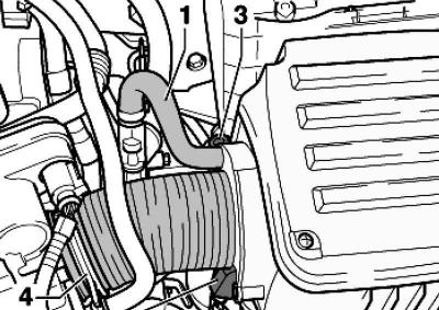
Disconnect the hoses and connector from the vacuum reservoir A and remove it (pic. 2.223).
Pic. 2.224. Intake air temperature sensor hose and connector
Disconnect the hose 1 and connector from the intake air temperature sensor 2 on the air filter housing (pic. 2.224).
Unscrew the bolt 3 and remove the air filter housing with the air inlet hose 4.
Remove the EGR connecting pipe between the intake manifold and the EGR valve.
Disconnect the electrical connectors on the intake manifold.
Disconnect the water hoses from the throttle control module.
Disconnect the crankcase ventilation hose at the valve cover and loosen the hose clamp between the intake manifold and the fuel rail.
Note: It is recommended to use CLIC clamp pliers to mount clamping collars.
Pic. 2.225. Intake manifold mounting nuts
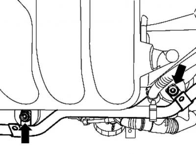
Loosen the intake manifold mounting nuts (pic. 2.225).
Pull the intake manifold up.
Installation is carried out in the reverse order.
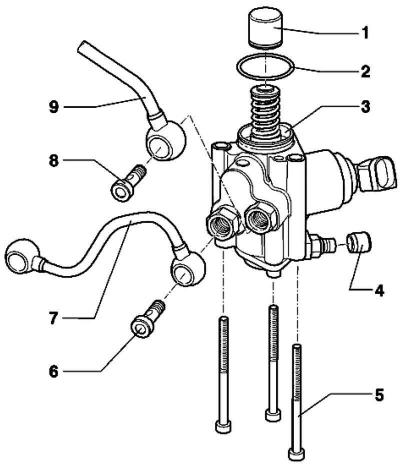
Pic. 2.226. High pressure pump components: 1 - pusher; 2 – O-ring; 3 - high pressure pump with fuel pressure control valve; 4 - protective cap for the air valve; 5 - bolt 10 Nm; 6 - fitting with a conical sealing surface, 15 Nm; 7 - high pressure pipeline; 8 - fitting with a conical sealing surface, 15 Nm; 9 - fuel line
Removal and installation of the high pressure pump
Note: Do not disassemble the high pressure pump
Note: Before starting installation work, take safety measures.
Removing
Bring the engine to TDC.
Remove the suction pipe.
Caution: Use safety precautions when relieving pressure in high pressure areas.
Remove fuel pipes. When disconnecting from the high pressure pump, support the fittings with a wrench.
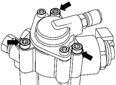
Pic. 2.227. Binder mounting bolts
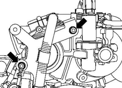
Loosen the binder (pic. 2.227).
Remove the high pressure pump.
Remove pusher from housing.
Installation
Replace the high pressure pump O-ring and moisten it lightly with clean engine oil.
Note: The high pressure pump must be installed with the mounting bolts already inserted.
Note: Install fuel lines without mechanical stress.
Check up a pusher on absence of damages and insert it into a head of the block of cylinders.
Pic. 2.228. High pressure pump mounting bolts
Carefully place the high pressure pump on the cylinder head and tighten the bolts by hand (pic. 2.228).
Install the fuel pipes. Then tighten all bolts without tightening them all the way.
Visitor comments