



Verification conditions
The minimum voltage on the battery should be 11.5 V.
Fuse SD34 in the fuse box on the right side of the front panel should be good.
The fuel pump control unit must be in good working order.
Engines with letter designation BLR, BLX, BLY
The low pressure fuel pressure sensor must be in good condition.
Note: The operation of the fuel pump is checked by diagnosing the actuators.
Connect tester A.
Insert the diagnostic system cable connector into the diagnostic connector in the driver's footwell area.
Turn on the ignition.
On the display, press the fields "Vehicle self-diagnosis", "01 – engine electronics" and "03 – diagnostics of actuators" in turn.
Press and hold the right arrow button on the display until "Fuel pump electronic actuator diagnostics" appears.
The fuel pump should then slowly increase its speed to maximum rpm.
Turn off the ignition.
If the fuel pump does not turn on, remove the bench seat.
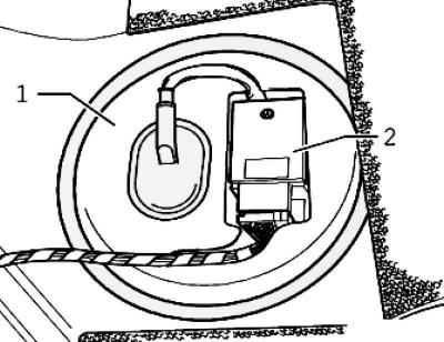
Fig. 2.204. Fuel supply module cover and control unit
Disconnect the fuel pump control unit connector (fig. 2.204).
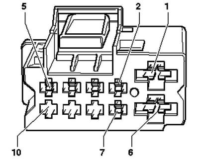
Fig. 2.206. Power connector pins
Check the power supply with a tester between pins 1 and 6 (fig. 2.206).
The LED should be on.
If the LED does not light, find the break in the circuit using the electrical diagram and fix it.
(The original article is posted on the website: VWManual.ru)
If the LED is on (the food is ok), remove the fuel supply unit.
Check if the electrical wires are connected between the flange and the fuel pump.
If no breaks in the connection are found, then the fuel pump is faulty and the fuel supply unit should be replaced.
Visitor comments