



Verification conditions
The minimum voltage on the battery should be 11.5 V.
Fuse SD34 in the fuse box on the right side of the front panel should be good.
The fuel pump control unit must be in good condition.
Engines BLR, BLX, BLY
The low fuel pressure sensor must be in good condition.
Verification procedure
Remove the rear seats.
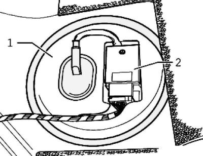
Fig. 2.204. Fuel supply module cover and control unit
Remove cover 1 with fuel pump control unit 2 from the fuel delivery module (fig. 2.204).
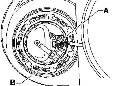
Fig. 2.205. Plug and fuel line
Disconnect the 5-pin plug from the flange (fig. 2.205).
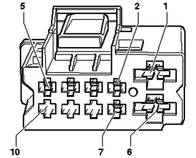
Fig. 2.209. Fuel pump connector
Connect the remote control via auxiliary wires to contact 1(+) of the fuel pump and to contact 1(+) – 10 of the connector (fig. 2.209).
Connect terminals 6 (–) – 10 of the connector and 5 (–) of the fuel pump with the auxiliary wire from the auxiliary measuring equipment kit.
Unscrew the fuel tank filler cap.
Disconnect the fuel supply line 2 and place a rag under the leaking fuel.
Note: To disconnect the fuel line, press the retaining ring.
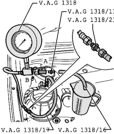
Fig. 2.210. Connecting the pressure gauge
Connect a pressure gauge with a double nipple and a set of adapters to the fuel supply line (fig. 2.210).
Place the hose adapter onto the gauge adapter and keep it pointed into the graduated container.
Caution: There is a risk of fuel splashing when opening the tap; to avoid injury and skin contact, wear protective glasses and gloves. Place a container under the open connection of the pressure gauge.
Open the pressure gauge valve. The lever indicates the flow direction A.
Use the remote control. At the same time, slowly close the tap until the pressure gauge shows 4 bar of excess pressure. After this, do not change the position of the tap.
Empty the measuring vessel.
Fuel pump performance depends on battery voltage. Therefore, connect the multimeter with wires from the auxiliary measuring kit to the battery.
Turn on the remote control for 30 seconds and measure the battery voltage.
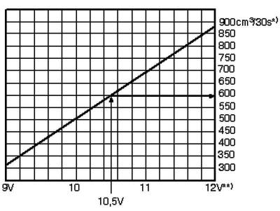
Fig. 2.211. Diagram of nominal fuel supply values
Compare the amount of fuel received with the nominal value (fig. 2.211).
Example:
During the test, the voltage measured on the battery is 12.5 V. Since the voltage on the pump is 2 V less than the battery voltage, the minimum delivery volume is about 580 cm³/30 s.
*) – Minimum productivity, cm³/30 s
**) – Voltage at the fuel pump with the engine off and the pump running (approximately 2 V less than the battery voltage).
If the specified pressure value is not reached, check the fuel line for kinks and blockages.
If the fault is not found, remove the fuel delivery module and check the strainer for contamination.
If no errors are found here either, replace the flange with the fuel filter
Please retry the check.
If the nominal value is still not reached, the fuel pump is faulty, replace the fuel delivery module.
Nominal fuel delivery performance has been achieved, but a fault in the fuel system is still possible (eg temporary failure of the power supply system)
Check the current consumption of the fuel pump.
Checking energy consumption
Verification procedure
Remove the rear seats.
Remove cover 1 with fuel pump control unit 2 from the fuel delivery module (fig. 2.204).
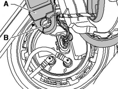
Fig. 2.212. Installation of heat measuring clamps
Connect the multimeter with current clamp A to wire B, pin 1 of the 5-pin connector (fig. 2.212).
Start the engine and let it idle.
Measure the power consumption of the fuel pump. Nominal value max. 9 A.
Note: If the error in the fuel system appears only from time to time, the check can also be carried out during a test drive, but this requires a second specialist.
If the power consumption is exceeded, then
the fuel pump is faulty, replace the fuel delivery module.
Visitor comments