
Note: Vehicles with BLY and BVZ engines comply with the EU emission standard 2. These vehicles do not have some components related to the exhaust system, such as the EGR system, Lambda probe 2 and Lambda probe 2 after the catalytic converter. This must be taken into account during installation work.
Note: The exhaust manifold is removed upwards.
Removing
Remove the noise screen.
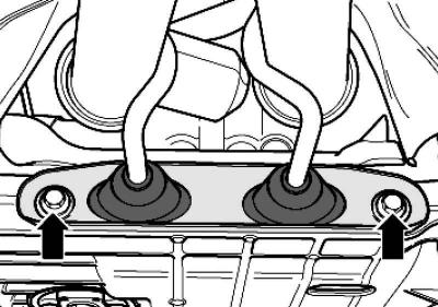
Pic. 2.88. Exhaust holder
Unscrew the exhaust system holder (pic. 2.88).
Note: On vehicles with engine codes BLX, BVX, the bracket for the exhaust system is removed together with the cable duct for the lambda probes behind the catalytic converter.
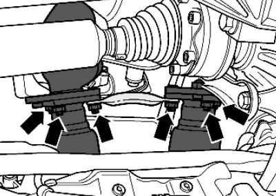
Pic. 2.90. Downpipe mount
Unscrew the nuts securing the intake pipe to the exhaust manifold (pic. 2.90).
Note: The split elements in the downpipe must not be bent more than 10°. There is a risk of damage.
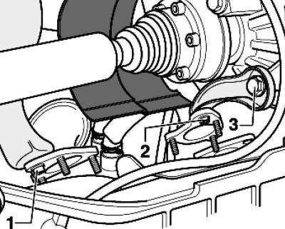
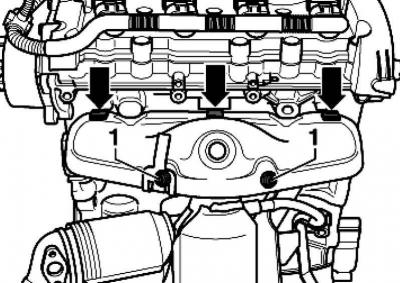
Pic. 2.237. Exhaust manifold support bolts
Unscrew the bolts 1..3 exhaust manifold supports (pic. 2.237).
Remove, if present, the engine cover.
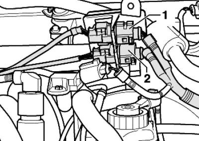
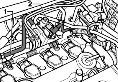
Pic. 2.238. Plug connections 1 and 2 lambda probes
Remove connectors 1 and 2 for the lambda probes from the holder and disconnect them (pic. 2.238).
Note: Engine code BVY has only one connector.
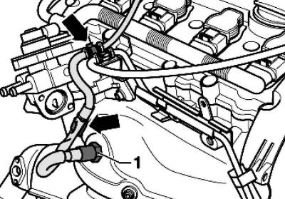
Pic. 2.239. Plug and water hose
Unlock water hose 1 and disconnect plug 2 (pic. 2.239).
BLR, BLX and BVX engines
Remove the wire box.
Continuation of assembly operations for all vehicles
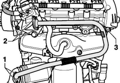
Pic. 2.240. Connecting pipe
Unscrew the bolts 1..3 and remove the connecting pipe (pic. 2.240).
Unscrew the fixing bolt.
Loosen the bolts on the intake manifold and remove the connecting pipe.
Release the lambda probe harness 1.
Pic. 2.241. Location of the lambda probe
Remove lambda probes 1 (pic. 2.241).
Note: Leave the water hoses from the EGR valve connected.
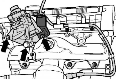
Pic. 2.242. Recirculation valve mount
Remove the EGR valve and put it aside (pic. 2.242).
Pic. 2.243. Protective screen attachment
Dismantle the protective screen above the exhaust manifold, for which unscrew the bolts 1 and remove the protective screen (pic. 2.243).

Pic. 2.244. exhaust manifold mounting
Remove the exhaust manifold and pull it up (pic. 2.244).
Installing the exhaust manifold
Installation is carried out in the reverse order, paying attention to the following.
All cable ties should be installed in their original locations.
Replace gaskets and self-locking nuts.
Lubricate the cylinder head and exhaust manifold dowel pins with heat-resistant paste.
Lubricate the threads of the lambda probes with heat-resistant paste; the paste must not get on the slots of the probe body.
Tightening torques
Exhaust manifold to cylinder head: 25 Nm
Protective screen to the exhaust manifold: 10 Nm.
Lambda probe: 55 Nm.
Bracket to auxiliary frame: 25 Nm.
Downpipe to exhaust manifold: 25 Nm.
EGR connecting pipe to EGR valve: 10 Nm.
EGR connecting pipe to exhaust manifold: 15 Nm.
Visitor comments