



Note: Vehicles with BLY and BVZ engines comply with the EU 2 exhaust emission standard. Some components of the exhaust system, such as the exhaust gas recirculation system, lambda probe 2 and lambda probe 2 after the catalytic converter, are not installed on these vehicles. This must be taken into account during installation work.
Removal the inlet pipe with the catalytic converter
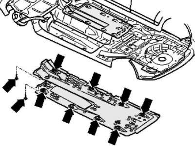
Fig. 2.245. Bottom protection
Remove the right underbody protection (fig. 2.245).
Vehicles with BLR, BLX, BVX and BVY engines
Remove the lambda probe plug connections from the holder and disconnect them.
Release the lambda probe wiring harness.
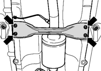
Fig. 2.246. Transverse support of the bottom
Remove the cross support from the bottom (fig. 2.246).
Cars with engine letter designation BLX, BVX
Disconnect the plug (black) from the NOx sensor control unit.
Remove the NOx sensor control unit and release the wiring harness with the control unit.
Disconnect the plug (black) for the exhaust gas temperature sensor and release the wiring harness.
Disconnect the plug (black) for the lambda probe after the catalytic converter and release the wiring harness.
Disconnect the plug (black) 4 for the lambda probe after the catalytic converter and release the wiring harness.
Remove the cross support from the bottom.
Continuation of installation operations for all vehicles
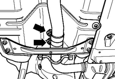
Fig. 2.247. Fastening the clamping clamp
Disconnect the exhaust system by loosening the clamp (fig. 2.247).
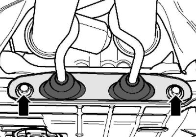
Fig. 2.88. Exhaust system holder
Unscrew the exhaust system holder (Fig. 2.88).
Note: On vehicles with BLX and BVX engines, the exhaust system bracket is removed together with the lambda probe cable box after the catalytic converter.
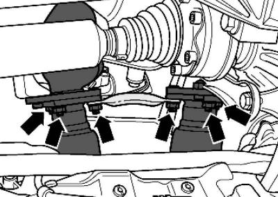
Fig. 2.90. Fastening the inlet pipe
Unscrew the nuts securing the inlet pipe to the exhaust manifold (Fig. 2.90).
Note: The detachable elements in the intake pipe must not be bent more than 10°. There is a risk of damage.
Remove the exhaust pipe with the catalytic converter.
Installing a downpipe with a catalytic converter
Installation is carried out in the reverse order, taking into account the following.
All cable ties should be installed in their original locations.
Replace gaskets and self-locking nuts.
Lubricate the exhaust manifold dowel pins with heat resistant grease
Lubricate the threads of the lambda probes and NOx sensor (in vehicles with BLX and BVX engines) heat-resistant paste; the paste should not get on the splines of the probe body.
Position clamp 2 so as to achieve dimension A between clamp 2 and mark on inlet pipe 3.
Note: There are 3 marks on the intake pipe.
Install the clamp so that the end of the bolt does not extend beyond the bottom edge of the clamp.
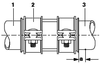
Fig. 2.248. Installation diagram of clamping clamps: 1 – intermediate muffler; 2 – clamping clamp; 3 – intake pipe; a – size a is approximately 5 mm
Tightening torques
Downpipe to exhaust manifold: 25 Nm.
Clamping clamp: 25 Nm.
Cross support to the bottom: 23 Nm.
Bracket to subframe: 25 Nm.
Note: Lubricate the exhaust manifold dowel pins with heat resistant grease
Visitor comments