



Contents: Removal ↓ Installation ↓
The fuel pump is located in the fuel tank and forms a single unit with the fuel gauge sensor.
The fuel gauge sensor consists of a float and a potentiometer.
When the fuel level drops, the sensor float also drops.
At the same time, the potentiometer on the float increases the electrical resistance of the sensor. As a result, the voltage supplied to the indicator on the instrument panel decreases, and the fuel gauge needle on the instrument panel deflects in the "leer" direction ("empty").
Attention! In cars with a gasoline engine with direct injection, the fuel pump control unit is located directly on the "pump and sensor" block.
Warning! When dismantling the fuel pump, some fuel may escape. Fuel vapors are toxic and flammable, so ensure good ventilation of the room and work area. Avoid contact with skin. Use protective gloves. Avoid open flames and keep a fire extinguisher at hand.
When dismantling the fuel pump and sensor, there should be no fuel in the fuel tank. If possible, use it up. As an exception, work may be carried out if the tank of a car with a gasoline engine is only 1/2 full, and with a diesel engine - 3/4 full. A centrifugal fan with an electric motor located outside the air flow and a capacity of 15 m³/hour can be used to ventilate the work area.
Removal
1. With the ignition off, disconnect the ground (-) wire terminal from the negative battery terminal.
2. Fold the rear seat forward or, if necessary, remove the rear seat or the right rear seat (golf Plus cars), see the relevant chapter.
3. Release and move back, if necessary, the floor covering under the rear seat.
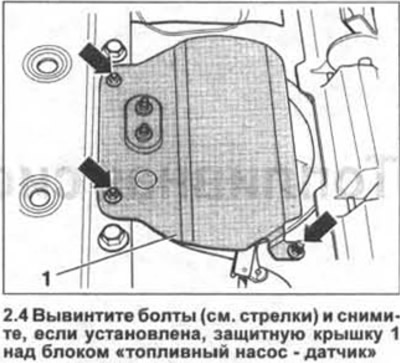
4. Unscrew the bolts (see arrows in the illustration) and remove, if installed, the protective cover 1 above the "fuel pump - sensor" unit.
5. Remove cover 1 above the fuel pump and fuel gauge sensor using a screwdriver (see illustration).
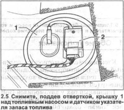
Attention! For vehicles with a petrol engine with direct fuel injection (FSI), the fuel pump control unit 2 is mounted on cover 1 (see illustration 2.5). There is no need to disconnect the power plug of the unit.
6. Carefully disconnect the fuel gauge and fuel pump connector by hand or by prying it out of its mount with a small screwdriver.
Caution! The fuel supply line is under pressure. Before disconnecting the fuel hoses, cover the joint with a rag. Disconnect the fuel hose slowly to relieve pressure in the system. Wear safety glasses when performing work.
7. Mark fuel hoses 1 and 2 with a felt-tip pen before disconnecting them (see illustration).
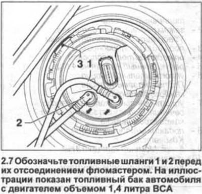
Disconnect the supply 2 and return 1 fuel lines by squeezing the clamp leashes at the connecting joints (see illustration 2.7). Seal the holes in the pipes with suitable plugs or wrap them with tape.
8. Golf cars: Loosen the tightening and then unscrew the union nut (see illustration). A special key is required to loosen the tightening.
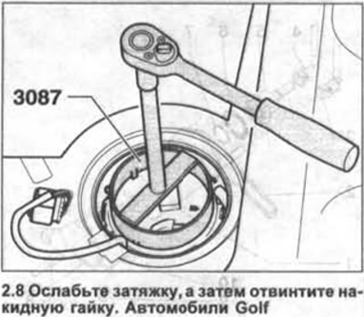
For cars with 1.4 liter engines and 1.4-/1.6 liter FSI, the VW-3087 key is used, and for all others, the VW-10202 key is used.
9. Touran vehicles: Unscrew the union nut by placing the special key VW-3217 on the three rounded projections of the union nut (see illustration).
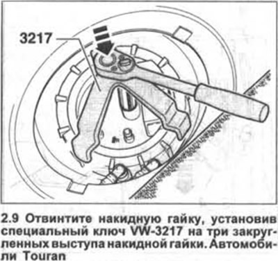
Caution: When turning the key, press on it from above to ensure a tight fit on the nut (see arrow in illustration 2.9).
Attention! If the above-mentioned special keys are not available, the union nut can be unscrewed using a wooden drift, striking it with a hammer. In this case, sparking is not allowed.
10. All-wheel drive vehicles with a 2.0-liter FSI engine.
Disconnect the feed pump line secured with coupling A (see illustration). To do this, press on the coupling lever B and disconnect the hoses.
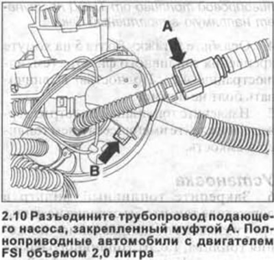
11. Carefully remove the fuel pump, fuel gauge sensor and sealing gasket from the fuel tank.
12. Drain the fuel from the pump back into the tank or into a separate suitable container.
13. Inspect the sealing gasket and if it is damaged or porous, replace it with a new one.
Installation
14. Install the flange sealing ring into the hole on the fuel tank. Do not wet the sealing ring with fuel. Wetting the mating surface of the ring is only necessary when installing the fuel pump together with the fuel gauge sensor.
15. Reinstall the fuel pump, being careful not to bend the fuel gauge sensor lever.
Caution! Observe the correct installation position of the fuel pump. Depending on the model, the reference marks on the pump flange may be positioned differently.
16. Golf cars with petrol engine and with diesel engine with a capacity of 2.0 liter BDK. Marking on sealing flange 3 (see illustration 2.6) must be facing rearward when viewed in the direction of vehicle travel. The flange can only be installed in this position. If necessary, carefully rotate the fuel pump.
17. Golf cars with 1.9-/2.0-liter diesel engine AVZ/BKD and Touran. Marking on the sealing flange (see arrow in illustration) should be installed opposite the mark on the fuel tank. If necessary, carefully tighten the fuel pump. The mark is quite difficult to see.
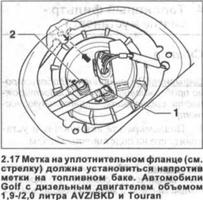
18. Screw on and tighten the fuel tank opening union nut using the special wrench.
Nut tightening torques:
- Golf cars - 110 Nm
- Touran cars - 80 Nm
Caution! If the special keys mentioned above are not available, the union nut can be tightened using a wooden drift and hitting it with a hammer. This will prevent sparking. Make sure the union nut is tightly tightened.
19. Connect the return 1 and feed 2 hoses, following the marks made before disconnecting them. The hoses have clamps that must be fixed. The arrows on the connecting flanges of the hoses indicate the direction of fuel flow (see also illustrations 2.6 and 2.16).
Attention! Do not confuse the return and supply hoses. They are different in color. The return hose is painted blue, and the supply hose is black.
20. Connect the multi-pin plug and secure it.
21. Make sure the fuel and vent hoses are secured to the clips on the tank. Tighten them if necessary.
22. Replace the fuel tank filler cap.
23. Secure the protective cover over the tank with bolts, if present.
24. Replace the floor covering under the rear seat.
25. Reinstall the rear seat, see the relevant chapter.
26. Connect the battery.
Attention! If the engine does not start after replacing the fuel pump, the fuel system should be bled through the vent hose fitting.
Visitor comments