
The electronic fuel injection system has its advantages, which are as follows:
- A) accurate dosing of the amount of fuel in each mode of engine operation, which ensures lower gasoline consumption while maintaining good dynamic performance!;
- b) reduction of harmful exhaust gases as a result of precise fuel dosing and exhaust gas cleaning (OG) with the help of a catalyst;
- V) self-diagnosis of the control unit, which allows you to quickly find the fault. The injection system is equipped «memory», where errors are recorded during the operation of the car. If during operation failures occur in the ignition or injection system, they are recorded. If a malfunction occurs in the operation of the engine in a specialized workshop, you can get a printout of faults for a fee in order to independently eliminate one or another defect if necessary.
The microprocessor that controls the motor is a small, fast computer.
It determines the optimum ignition timing, fuel injection timing and injected fuel volume. In this case, the actions of the microprocessor are coordinated with control units of other vehicle systems, for example, with a gearbox control unit or with an anti-theft system.
All parts of the ignition and fuel injection systems are designed for a long service life and practically do not require repair.
As part of the maintenance, it is only necessary to change the removable filter element of the air filter, as well as the spark plugs. Basic adjustment and repair work can only be carried out using expensive instrumentation. For this reason, repairs and adjustments should be entrusted to specialized workshops with the necessary instruments and devices.
Precautions awn
Attention! The fuel system is under pressure. Before disconnecting the fuel system hoses, wrap the junction of the hoses with a rag and only then carefully remove the hose, relieving pressure.
Attention! For vehicles with direct injection engines, the pressure can only be relieved in that part of the system where a relatively low pressure is created (up to 5 bar). To relieve pressure in the part where high pressure is injected (up to 100 bar), requires special equipment, available only in workshops. The high pressure fuel system includes the high pressure pump, high pressure lines and fuel injectors.
No open flames or sparks near the workplace! Smoke up!
The workplace must be equipped with a fire extinguisher!
Ensure good ventilation of the work area. Fuel fumes are poisonous.
Attention! When working on the injection system, the general safety and cleanliness rules must be observed, see section «Fuel system».
Sensors and actuators of the injection system
Fuel is drawn from the fuel tank by an electrically driven fuel pump and fed through a bottom mounted fuel filter to the fuel injectors.
Depending on the type of engine, the pressure reducing valve ensures a constant pressure of approx. 4.0 bar in the fuel system.
Fuel is supplied through electronically controlled valve injectors, i.e. intermittently injected into the corresponding intake manifold pipe just before the engine intake valves.
The engine control unit regulates the sequence and duration of the injection and thus the amount of fuel injected.
Air is taken in by the engine through the air filter and through the throttle valve and intake manifold to the intake valves. The intake air volume is controlled by a throttle valve actuated by a stepper motor at the command of the engine control unit.
The engine control unit is located in the engine compartment on the left side on the dividing wall. The block is a small fast working computer. It determines the optimum ignition timing, the timing of fuel injection will beat the injected fuel.
The information received by the electronic unit from sensors, as well as the commands given to the actuators or control mechanisms, ensure optimal engine operation in any situation that develops at the moment of movement.
If one or more of the main sensors fails, the control unit executes an emergency program to reduce the danger to the engine and ensure continued movement.
In such cases, the engine starts to work intermittently and when you press the accelerator pedal, it may stall.
Sensors and actuators of the fuel injection system
Fuel tank ventilation is carried out using a container with activated carbon and a solenoid valve, also called a regeneration valve. Activated carbon absorbs fuel vapors that form in the tank as a result of fuel heating. When the engine is running, the fuel absorbed by the coal is released and it enters the engine for combustion.
Pressure meter in the intake manifold and the intake air temperature sensor are in the same housing, which is screwed into the intake manifold.
Both sensors register and report to the engine control unit information about the current load on the engine.
Based on this information, the unit calculates the amount of fuel to be injected. For 1.4-/1.6-litre FSI engines, the intake air temperature sensor is located in the intake duct on the top engine cover.
Lambda probe (oxygen sensor) is designed to control the operation of the catalyst, determining the oxygen content in the exhaust gas and transmitting the relevant information to the engine control unit by changing its voltage.
As a rule, two lambda probes are installed on Golf/Touran vehicles. By means of signals from a second lambda probe, which is installed after the catalyst, the functioning of the catalyst is checked.
knock sensor located on the side of the cylinder block and serves to prevent detonation combustion of fuel, maintaining the optimum ignition timing. In this way, the energy resulting from the combustion of the fuel is better used and fuel consumption is reduced.
Electronic accelerator
Instead of a conventional cable from the accelerator pedal, a pedal position sensor is installed on it, which tells the engine control unit the position of the pedal at the current moment.
Based on the received signals, the control unit sets the opening angle of the throttle valve, which is driven by the executive motor.
In the sensor housing on the accelerator pedal, there are two contact potentiometers mounted on one shaft (see illustration 1.0).
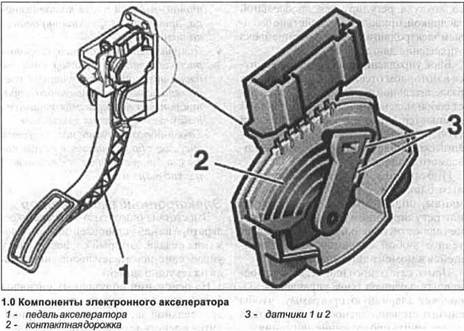
With a change in the position of the pedal, the resistance of the potentiometers changes and, accordingly, the voltage of the signal coming from them to the control unit.
In the event of a failure of one of the sensors, the electronic accelerator warning light comes on, and the self-diagnosis unit registers the malfunction. If both sensors fail, the engine starts to work with an increased idling speed and does not respond to a change in the position of the pedal.
Throttle block
The throttle valve is an integral element of the control unit, which is responsible for many functions (see illustration 1.0a).
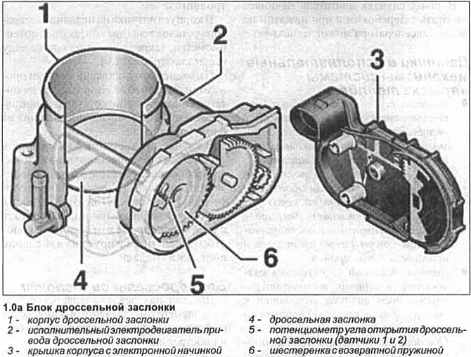
The main task of the block is to stabilize the idle speed of the engine under any operating conditions and under any load on it, for example, by turning on the air conditioner or when the power steering is activated.
The throttle actuator consists of an electric motor, a gear system with a return spring.
The actuator regulates the position of the throttle valve. This ensures that the idle speed is constant, regardless of whether additional power consumers of the engine, such as power steering or air conditioning compressor, are turned on.
The throttle valve opening angle potentiometer is mounted on the valve shaft and transmits the throttle position at each current moment to the engine control unit.
The second potentiometer reports the control data to the control unit and acts as a spare in case of failure of the first sensor.
FSI petrol engine (direct fuel injection)
FSI engines have stratified injection of fuel directly into the combustion chambers of the cylinders, and not into the intake manifold pipe.
Conventional internal combustion engines are designed for a homogenized air-fuel mixture, while engines with direct injection, when driving within a certain speed range, operate on a stratified mixture with an increased proportion of air.
Thus, at speeds up to 70 kilometers per hour, a reduction in fuel consumption is achieved.
In volume, in engines with direct injection, two methods of forming an air-fuel mixture are implemented: layer-by-layer when driving at speeds up to 70 kilometers per hour, and homogenized at high speeds.
To implement these methods requires a significant use of electronics. In addition, the requirements for the mechanical part of the engine are much higher in comparison with a conventional internal combustion engine.
For example, the intake tract is two-channel. When a layered mixture is supplied, the damper closes the lower intake tract so that the intake air is accelerated in the upper tract and swirled into the cylinder. Additionally, the flow is accelerated by a recess in the piston chamber. Just before ignition on the compression stroke (40-120 bar) fuel is directly injected into the combustion chamber.
The fuel system consists of two parts - low and high pressure.
In the low pressure part of the fuel system, fuel is taken and supplied by an electric fuel pump at a pressure of about 4 bar (maximum 6 bar when starting a cold or hot engine) through the fuel filter to the high pressure fuel pump.
In the high-pressure part of the fuel system, fuel at a pressure of 40-120 bar flows from the injection pump to the fuel line, and from there it is distributed among four solenoid fuel injectors.
Due to the fact that when using a layered mixture, due to the high proportion of air in it, the content of nitrogen oxides increases significantly (NOx) in the exhaust gas, then along with a three-channel catalyst, an additional catalyst is required to accumulate these oxides.
This additional catalyst is identical in design to the three-channel one, but its surface is additionally covered with barium oxide, which at temperatures from 250°C to 500°C results in the conversion of nitrogen oxides into nitrates, which are deposited on the catalyst.
The capacity of the catalyst is limited, therefore, before filling the catalyst, a switch is made to the supply of a homogenized mixture in order to burn the deposits accumulated in the catalyst.
Idling, ignition timing, CO content - check and adjust.
As part of maintenance, adjustment of idle speed, ignition timing and CO content is not required, because they are constantly monitored electronically.
If the actual performance differs from the nominal, then the reason for this is a malfunction of the electronic parts that must be replaced.
A qualified check of the functioning of engine systems is possible only with the use of special instrumentation.
Visitor comments