
Removing
1. Remove the top protective cover from the engine.
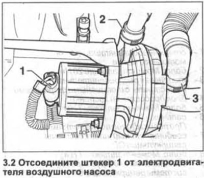
2. Disconnect plug 1 from the air pump motor (see illustration).
3. Vehicles with BGU engine. Remove the mounting bolts and remove the air pump.
4. Remove the engine oil dipstick and funnel from the guide tube and disconnect them from the air pump bracket.
5. Disconnect the air pump bracket by unscrewing bolts 1, 2 and 3 (see illustration).
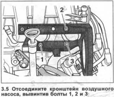
Attention! For BSE/BSF motors, the bracket is not detachable and is removed together with the motor.
6. Vehicles with BGU engine. Loosen the tension of the ribbed belt and lock the tension roller with the thrust roller.
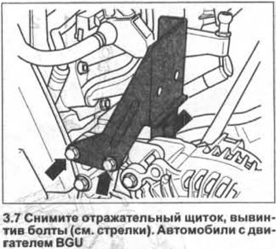
7. Vehicles with BGU engine. Remove the deflector by unscrewing the bolts (see arrows in illustration).
8. Vehicles with BGU engine. Remove spacers 1 (see illustration).
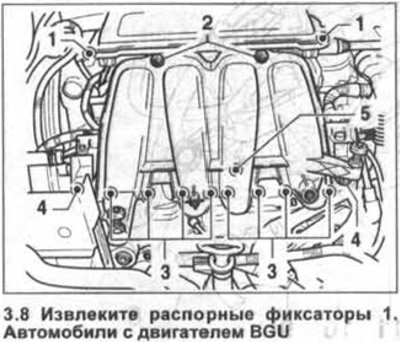
9. Unscrew two bolts 2 (see illustration 3.8).
10. Unscrew the bolts / nuts 3 and 5 securing the lower part of the intake manifold to the cylinder head (see illustration 3.8).
Unscrew the bolts 4 on the fuel distribution line and remove the spacers that secure the wire harness guide to the fuel distribution line (see illustration 3.8).
12. Carefully wring out both ledges on the top part of an inlet collector and disconnect the lower part from it, having submitted downwards. At the same time release the fuel distributive highway with the nozzles fixed on it from the bottom part of a collector.
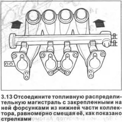
13. Disconnect the fuel distribution line with the nozzles attached to it from the lower part of the manifold, evenly shifting it, as shown by the arrows in the illustration, and place it on a clean rag.
Installation
Installation of dismantled parts is carried out in the reverse order of removal. In doing so, the following points should be taken into account and paid attention to:
14. Replace O-rings between intake manifold and cylinder head.
15. Replace O-rings between injectors and intake manifold. Before installing new rings, lubricate them with a thin layer of engine oil.
16. Fix the fuel distributive highway together with the established atomizers on the bottom part of an inlet collector, without allowing a distortion.
Tightening torques for threaded connections
- manifold to cylinder head - 25 Nm
- bolts of the connecting joint of the upper and lower parts of the collector - 3 Nm
- fuel distribution line to intake manifold - 8 Nm
Visitor comments