
English Русский
Български
Беларускі
Український
Српски
Hrvatski
Română
Polski
Slovenský
Magyar
  |  Articles  |  Sitemap  |  Contacts  |    |
Car maintenance Ford Car maintenance Hyundai Car maintenance Chevrolet Car maintenance BMW Car maintenance Audi Car maintenance Opel Car maintenance AvtoVAZ
VWmanual.ru


Main   Passat   Golf   Polo   Touareg   Tiguan   Sharan   Transporter   Others  
Golf 1 (1974-1984, diesel) Golf 1 (1974-1984, petrol) Golf 2 (1984-1993, petrol) Golf 2 (1984-1993) Golf 3 (1991-1997) Golf 4 (1997-2004) Golf 5 (2003-2008)

Exhaust system — removal and installation (VW Golf 5)

  • Main
  • Golf
  • Golf 5
  • Power unit
  • Fuel system
  • Exhaust system — removal and installation
            0


Contents: Removal ↓ Installation ↓ Some features of exhaust systems ↓

Removal


Attention! All exhaust system parts can be replaced separately. In this case, you will need to disconnect the main and additional mufflers by cutting the connecting pipe along the marks on it with a pipe cutter.


Warning! Raising the vehicle with a jack and placing it on jack stands is dangerous. Please read the safety precautions in Chapter "Jacking up a car".


1. Place the vehicle on jack stands.

2. Remove the engine splash guard.

3. Treat all exhaust system mounting bolts and nuts with rust remover and let it work.

4. Cars with petrol engines. Disconnect the lambda probe connectors.

5. Vehicles with FSI petrol engine: Disconnect the connectors of the exhaust gas temperature sensor and the nitrogen oxide sensor, if present, then unscrew the bolts and remove the unit from these sensors.

6. Vehicles with 1.6L petrol engine BGU/BSE/BSF Remove the right drive shaft heat shield.

7. Disconnect the exhaust system cross support, if present.

8. Disconnect, acting in accordance with the engine type, the inlet pipe near the catalytic converter from the exhaust manifold or turbocharger.

9. Support the exhaust system or secure it with wire to the underbody so that it does not fall off after disconnection.

Caution! The flexible connection element of the inlet pipe must not be bent at an angle greater than 10°, because the element will be damaged in this case.


10. Remove the exhaust system, working with an assistant.


Attention! The exhaust system components can be removed individually. If the connecting elements or bolts do not separate or unscrew, heat the exhaust pipe at the joint with a burner, placing an aluminum sheet to protect the bottom.


Warning! Use caution. Fire hazard.


Installation


Attention! Replace seals, nuts and bolts with new ones without fail. To ensure that the exhaust pipe mounting nuts and bolts can be unscrewed without problems later, it is recommended to lubricate them with a protective paste that is resistant to high temperatures, such as Liqui Moly-3080. Check the condition of the rubber rings of the exhaust pipe suspension and replace them with new ones if necessary.


If the pipes of the system are not being changed, then before connecting them, clean the mating surfaces with sandpaper, removing carbon deposits and remnants of sealing compound.

11. Connect the exhaust pipes. Tighten the mounting bolts by hand.

The connecting clamps must be installed so that the bolts on them are facing backwards or, when looking in the direction of travel of the vehicle, to the right.

12. Using the help of an assistant, secure the exhaust pipe to the suspension eyes and support it.

13. Secure the system with brackets or supports.

14. Connect the inlet pipe to the catalytic converter, to the exhaust manifold or turbocharger, installing a new sealing gasket.

15. Secure the pipe support bridge if it was removed. The tightening torque for the support bridge bolts is 35 Nm.

16. Vehicles with petrol engine BGU/BSE/BSF. Install the drive shaft heat shield. The tightening torque of the shield bolts is 35 Nm.


(The information is available on the website: www.vwmanual.ru)

17. Loosen the bolts of the connecting clamps and place the clamps at the joint as shown in the illustration. In this case, the lower edge of the bolt (see arrow in illustration) should not extend beyond the bottom edge of the clamp.
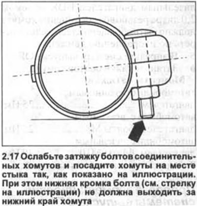
17. Loosen the bolts of the connecting clamps and place the clamps at the joint as shown in the…


18. Straighten the exhaust system in the suspension elements so that its pipes are positioned without stress. In doing so, ensure that the pipes of the system are at least 25 mm away from the body. If necessary, shift the system in the longitudinal direction. The load on the suspension elements of the pipes must be the same. Make sure that the pipes at the joint are seated deep enough in the connecting clamps. Use the corresponding support notches on the pipes as a guide.

19. Tighten all bolts and nuts, see the corresponding illustrations for tightening torques.

The M8 bolts of the connecting clamps are tightened with a force of 25 Nm, and the M10 bolts - 40 Nm.

20. Cars with gasoline engines. Install the nitrogen oxide content and exhaust gas temperature sensor unit, if present and removed.

21. Replace the engine mudguard (protection).

22. Lower the car onto its wheels.

23. Check the exhaust system for leaks.

Some features of exhaust systems


24. Vehicles with 1.6 litre petrol engine BGU/BSF/BSE: Secure the downpipe to the exhaust manifold with new self-locking nuts to a tightening torque of 25 Nm (see illustration).
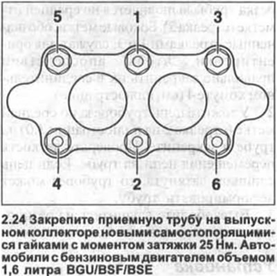
24. Vehicles with 1.6 litre petrol engine BGU/BSF/BSE: Secure the downpipe to the exhaust manifold…


25. Vehicles with 2.0 litre (T)FSI engine and 1.6 litre petrol engine BGU/BSF/BSE. After aligning, move the exhaust pipes forward until the tension of the muffler suspension eye is a = 5-11 mm (see illustration).
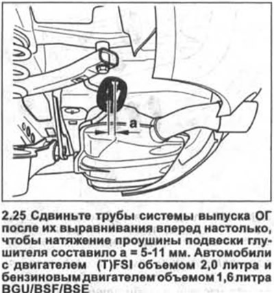
25. Vehicles with 2.0 litre (T)FSI engine and 1.6 litre petrol engine BGU/BSF/BSE. After aligning,…


Diesel Engine Cars


26. Position the connecting clamp so that the distance to the mark on the catalyst pipe is a = 5 mm (see illustration).
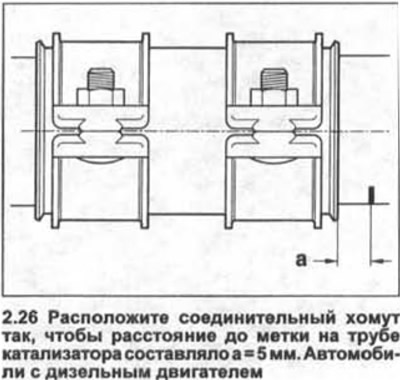
26. Position the connecting clamp so that the distance to the mark on the catalyst pipe is a = 5 mm…


27. Push the muffler pipe into the connecting clamp so that the distance a is equal to 15-17 mm (see illustration).
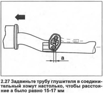
27. Push the muffler pipe into the connecting clamp so that the distance a is equal to 15-17 mm…


28. Straighten the exhaust pipes so that they are horizontal.

This article is available at russian, bulgarian, belarusian, ukrainian, serbian, croatian, romanian, polish, slovak, hungarian
The text has been checked: Kolesnikov Artem

Share information:

Previous articles
General information about the exhaust system
Air filter — removal, installation and disassembly
Fuel filter — removal and installation
Fuel gauge sensor — removal and installation
Fuel Pump and Fuel Gauge Sensor — Removal and Installation
General provisions on the fuel system
Next articles
Main and additional mufflers — replacement


Similar articles from other manuals for VW cars:
Instructions for vehicles with a catalytic converter in the… Passat B3 (1988-1993)
Exhaust gas system Polo 3 (1995-2003)
Exhaust system alignment Touareg 1 (2002-2006)
Catalyst and exhaust system attachments Tiguan 1 (2007-2015)
Removal and installation of the exhaust system Sharan 1 (1995-2000)
Engine and exhaust system Transporter T4 (1990-2003)
Exhaust system parts and components (BCA engines) Caddy 3 (2003-2010)
Link to this page in different formats


Visitor comments


No comments yet


How much will 18 + 38 =


Golf 5 
  • General information
  • User manual
  • Maintenance
  • Troubleshooting
  • Power unit
  • Engine repair
  • Cooling and ventilation system
  • Fuel system
  • Ignition system
  • Transmission
  • Clutch
  • Mechanical gearbox
  • Automatic gearbox
  • Chassis
  • Brake system
  • Car suspension
  • Steering
  • Body
  • Interior (internal elements)
  • Exterior (external elements)
  • Doors and covers
  • Electrical equipment
  • Power devices
  • Washers and wipers
  • Lighting and appliances
  • Electrical circuits
Golf 4 
  • General information
  • User manual
  • Weekly checks
  • Maintenance
  • Power unit
  • Petrol engines
  • Diesel engines
  • Cooling system
  • Fuel system (petrol)
  • Control system (petrol)
  • Fuel system (diesel)
  • Exhaust system
  • Transmission
  • Clutch
  • Car gearbox
  • Drive shafts
  • Chassis
  • Car suspension
  • Steering
  • Wheels and tires
  • Brake system
  • Body
  • Exterior (external elements)
  • Interior (internal elements)
  • Ventilation and heating
  • Car doors and sunroof
  • Washers and glass cleaners
  • Electrical equipment
  • Power devices
  • Lighting and appliances
  • Electrical circuits
Golf 3 
  • Petrol engine
  • Engine repair
  • Lubrication system
  • Cooling system
  • Ignition system
  • Diesel engine
  • Engine repair
  • Diesel injection system
  • Pre-glow system
  • Transmission
  • Clutch
  • Gearbox and drive shafts
  • Chassis
  • Steering
  • Wheels and suspension
  • Brake system
  • Electrical equipment
  • Lighting and appliances
  • Electrical circuits
Golf 2 
  • General information
  • Introduction to guide
  • User manual
  • Petrol engines 1.3 l
  • Engine repair
  • Lubrication system
  • Cooling system
  • Carburetors
  • Supply system
  • Ignition system
  • Petrol engines 1.6/1.8 l
  • Engine repair
  • Supply system
  • Ignition system
  • Diesel engines
  • Engine repair
  • Lubrication system
  • Cooling system
  • Power and exhaust system
  • Transmission
  • Clutch
  • 4-speed gearbox 084
  • 5-speed gearbox 085
  • 4-speed gearbox 020/4R
  • 5-speed gearbox 020/4T
  • Automatic gearbox
  • Drive shafts
  • Chassis
  • Steering
  • Car suspension
  • Brake system
  • Body
  • Body elements
  • Doors, locks and windows
  • Electrical equipment
  • Equipment and devices
  • Power devices
Golf 2 (petrol) 
  • General information
  • Characteristics
  • Car care
  • Maintenance
  • Power unit
  • Engine repair
  • Engine 1.05/1.30
  • Engine 1.60/1.80
  • Cooling and lubrication system
  • Power and exhaust system
  • Transmission
  • Clutch
  • Car gearbox
  • Drive shafts
  • Chassis
  • Brake system
  • Steering
  • Suspension
  • Body
  • Body and equipment
  • Electrical equipment
  • Lighting and appliances
  • Electrical circuits
Golf 1 (petrol) 
  • General information
  • Characteristics
  • User manual
  • Maintenance
  • Power unit
  • Engine adjustment
  • Engine 1.1/1.3
  • Engine 1.5/1.6/1.8
  • Engine electrical equipment
  • Cooling system
  • Fuel system
  • Transmission
  • Clutch and manual gearbox
  • Automatic gearbox
  • Chassis
  • Steering
  • Front suspension
  • Rear suspension
  • Brake system
  • Electrical equipment
  • Lighting and appliances
  • Electrical circuits
  • Body
  • Body and equipment
  • Optional equipment
Golf 1 (diesel) 
  • General information
  • Specifications
  • Maintenance
  • Power unit
  • Engine repair
  • Exhaust and turbocharger
  • Cooling system
  • Fuel system
  • Fuel injection system
  • Transmission
  • Clutch and drive shafts
  • Car gearbox
  • Chassis
  • Suspension and wheels
  • Steering
  • Brake system
  • Wheels and tires
  • Body
  • Heating and ventilation
  • Exterior (external elements)
  • Interior (internal elements)
  • Doors and windows
  • Electrical equipment
  • Equipment and devices
  • Lighting system
  • Power devices
  • Electrical circuits
VWmanual.ru © 2016-2026 | Mobile version | News and articles | Sitemap: EN BG BY UA RS HR RO PL SK HU | Write message | Site search
Passat B2 • Passat B3 • Passat B4 • Passat B5 • Passat B6 • Golf 1, diesel • Golf 1, petrol • Golf 2, petrol • Golf 2 • Golf 3 • Golf 4 • Golf 5 • Polo 3 • Polo 4 • Touareg 1 • Tiguan 1 • Sharan 1 • Transporter T3 • Transporter T4 • LT 28 • LT 2D • Beetle • Caddy 3 •
Our website uses cookies to ensure functionality and convenience.