
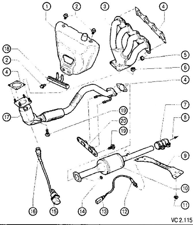
List of parts and assemblies of the exhaust system with technological notes to figure VC2.115:
1. Heat shield.
2. Screw securing the heat shield to the exhaust manifold: 10 Nm.
3. Exhaust manifold.
4. Gasket:
- replace during reassembly.
5. Nut for fastening the exhaust manifold to the cylinder head: 25 Nm:
- replace during reassembly.
6. Nut for fastening the exhaust manifold to the primary catalytic converter: 40 Nm:
- replace during reassembly.
7. Clamp, front 25 Nm:
- Align the exhaust system freely when cold before tightening;
- Tighten the clamp bolts evenly.
8. Direction to the intermediate muffler.
9. Front traverse.
10. Main catalyst.
11. Traverse fastening nut: 23 Nm.
12. Lambda probe after the catalyst (C130):55Nm:
- lubricate only the thread with heat-resistant grease (G 052 112 AZ). Heat-resistant grease must not get on the splines of the probe body.
13. Connector 4-pin lambda probe after the catalyst (G130) is located under the bottom lining on the right side.
14. Nut of fastening of the main catalyst to the primary catalyst: 25 Nm.
15. Connector 6-pin lambda probe in front of the catalyst (G39).
16. Lambda probe (G39) (before the catalyst): 55 Nm:
- lubricate only the thread with heat-resistant grease (G 052112 AZ); heat-resistant grease must not get on the splines of the probe body.
17. Pre-catalyst with downpipe exhaust system:
- protect against shock and impact loads.
18. Location of pipelines and wiring.
19. Screw: 25 Nm.
20. Fastening the exhaust system to the body.
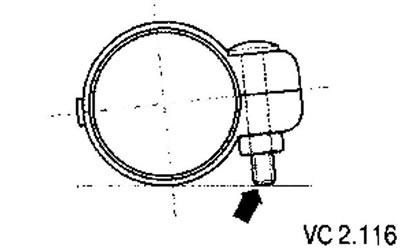
Mounting position of the front clamp:
- The connecting sleeve must be installed so that the ends of the bolts do not protrude beyond its lower edge (arrow).
- Threaded connection points to the right.
Visitor comments