
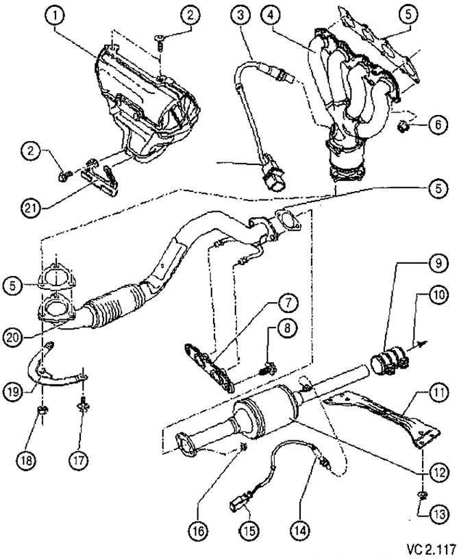
List of parts and assemblies of the exhaust system with technological notes to figure VC2.117:
1. Heat shield.
2. Screw securing the heat shield to the exhaust manifold: 10 Nm.
3. Lambda probe (G39): 55 Nm:
- lubricate only the thread with heat-resistant grease (G 052 112 AZ). Heat-resistant grease must not get on the splines of the probe body.
4. Exhaust manifold with primary catalytic converter.
5. Primary Catalyst to Exhaust Pipe Connection Gasket:
- replace during reassembly.
6. Heat shield to exhaust manifold nut: 25 Nm:
- replace during reassembly.
7. Fastening the exhaust system to the body.
8. Screw for fastening the exhaust system to the body 25 Nm.
9. Clamp, front: 25 Nm:
- before tightening, align the exhaust system freely in a cold state;
- Tighten the clamp bolts evenly.
10. Direction to the intermediate muffler.
11. Tunnel bridge ahead.
12. Main catalyst.
13. Traverse mounting nut: 23 Nm.
14. Lambda probe after the catalyst (G130): 55 Nm:
- lubricate only the thread with heat-resistant grease (G 052 112 AZ). Heat-resistant grease must not get on the splines of the probe body.
- the connector is located under the bottom cover on the right side.
15. Connector 4-pin.
16. 25 Nm.
17. 20 Nm.
18. Fastening nut: 40 Nm:
- replace during reassembly.
19. Bracket.
20. Exhaust pipe:
- with detachable element;
- the detachable element must not be bent more than 10°- risk of damage!
21. Location of pipelines and wiring.
Visitor comments