
Fuel pump and fuel tank gauge
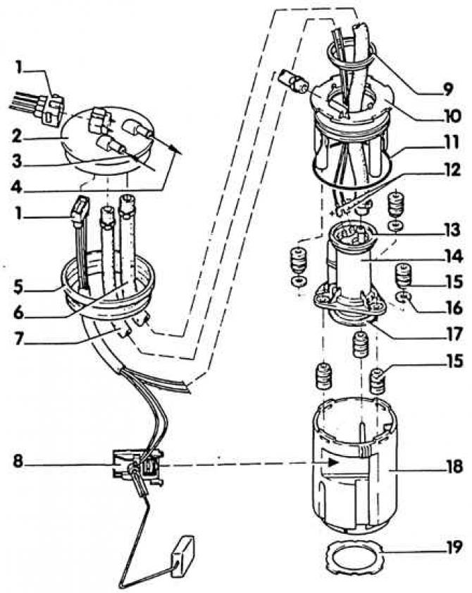
1. Connecting plug; 2. Flange. Pay attention to the fuel supply and return hose on the underside; 3. Fuel return. From the fuel distributor; 4. Fuel supply. To fuel filter.; 5. O-ring; 6. Fuel supply hose; 7. Fuel return hose; 8. Fuel gauge; 9. Top retaining ring; 10. Upper body; 11. Ring; 12. Fuel pump connector; 13. Top O-ring; 14. Fuel pump. With mesh filter and non-return valve; 15. Rubber support; 16. Washer; 17. Bottom O-ring; 18. Lower part of the body; 19. Ring
The fuel pump, together with the fuel gauge, is located in the fuel tank of a gasoline engine. In the diesel engine, the fuel pump is built into the high pressure fuel pump (injection pump), fuel gauge on top, on the fuel tank.
The fuel gauge consists of a float and a potentiometer. When the fuel level drops, the fuel sensor float also drops. A float connected to the potentiometer increases the electrical resistance of the sensor. As a result, the voltage on the instrument showing the fuel level drops, and the arrow indicating the fuel level deviates in the direction "leer" - empty.
Warning! When removing the fuel pump, a small amount of fuel may leak out. Fuel vapors are poisonous and highly flammable, so ensure that the workplace is well ventilated. Do not use open flame, fire hazard!
Removing
1. Disconnect ground cable (-) from the battery.
Attention! At the same time, the anti-theft code and tuned radio stations are erased from the radio memory. The battery must not be disconnected with the ignition on, otherwise the fuel injection system control unit will fail. Before disconnecting, read the instructions in subsection 10.11.1 and subsection 10.19.11.
2. Cut the carpet at the perforation to the right of the handbrake lever.
3. Unscrew the guard.
4. Disconnect the connecting plug of the fuel sensor and the fuel pump, to do this, lift the lateral locking tabs with a small screwdriver.
5. Loosen the clamps and disconnect the fuel supply and return pipes.
Attention! To facilitate installation, mark the fuel lines with adhesive tape.
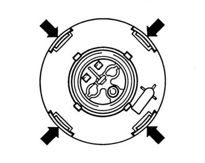
6. Unscrew the union nut with the special tool VW-3217. If there is no tool at hand, unscrew the bayonet cap with light hammer blows on the wooden rod.
Attention! There shouldn't be sparks.
7. Remove the flange and O-ring from the fuel tank opening.
8. Turn to the left to release from the bayonet lock and remove the fuel supply unit.
Attention! Before removing, place a rag to collect escaping fuel.
9. Remove the fuel sensor from the bottom of the housing.
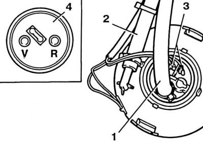
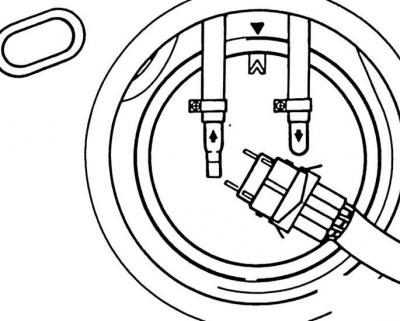
10. Disconnect the fuel supply hose (1), fuel return hose (2) and fuel pump connector (3) (4 - designation on the underside of the flange).
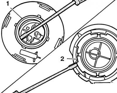
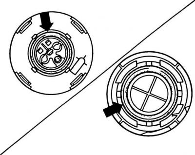
11. Remove the top retaining ring with a screwdriver (1) and bayonet ring (2) (on the bottom of the case).
12. Open the top of the housing with a screwdriver (arrows) and take it out from the bottom.
13. Remove the fuel pump from the bottom of the housing.
Installation
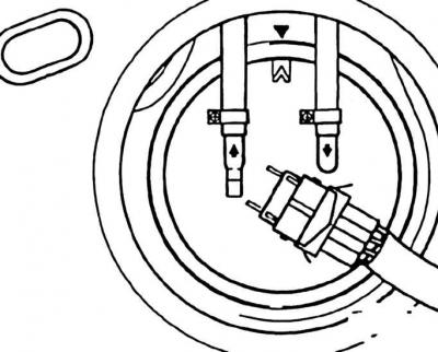
1. Install the fuel pump O-rings at the top and bottom (arrows) at the top and bottom of the case. Secure the upper sealing ring with a retaining ring, the lower sealing ring with a bayonet ring.
2. When assembling, lubricate the ring of the upper part of the housing with oil.
3. Put on the fuel supply and return hoses and secure with clamps. When doing this, pay attention to the designation on the underside of the flange (4) - see fig. in paragraph 10.
4. Install the fuel supply unit in the fuel tank, turn to the right, thereby locking it in the bayonet lock.
Attention! Do not bend the fuel sensor while doing this. The fuel gauge should point forward at about 30°.
5. Lubricate with oil and install the flange seal.
6. Install the flange so that the marking on the flange matches the marking on the fuel tank.
7. Fit and tighten the union nut.
8. Put on the fuel supply and return hoses and secure with clamps.
9. Insert plug.
10. Install a fence.
11. Set the carpet in place, glue or secure with adhesive tape.
Visitor comments