
Disassembly
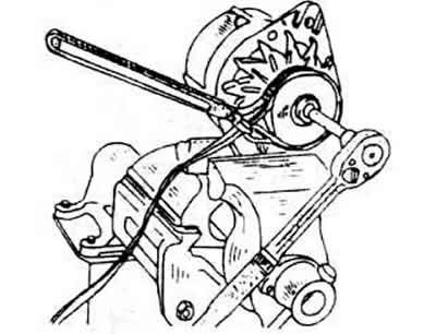
Unscrew the nut from the rotor shaft and pull the belt pulley, fan and spacer from the shaft. During dismantling, the shaft can be supported by winding the old V-belt around the pulley and holding it in a vise. To remove the belt pulley, a two- or three-arm puller is required. Please note that the built-in belt pulley is suitable for the respective motor.
Remove the key from the shaft.
Unscrew the regulator together with the traverse brush and remove it.
Mark the drive bearing shield and housing against it and remove both tension bolts from the housing, disconnect the rear bearing cap from the front. To do this, you can lightly tap on the front cover with a plastic hammer.
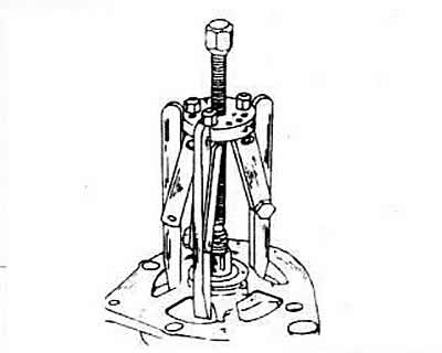
Place the bearing shield and rotor under a press and remove the rotor using a three-arm puller. The bearing base plate screws will pull out once the rotor has been pressed out. Therefore, by all means pay attention to the fact that the three arms are brought under the bearing base plate, and not just under the bearing shield. If it is necessary to remove the bearing from the shield, disconnect the screws from the inside and immediately press the bearing out.
Press the bearing off the end of the rotor slip ring. If it is necessary to use a pull-out tool for this, slide it under the inner ring of the bearing.
Unsolder the diode stand from the stator. To do this, clasp the wires in the solder zone between the stator and the soldering iron with tongs, which will thereby ensure heat dissipation, the diodes should not overheat.
Rectifier diodes should only be dismantled with the appropriate equipment and professional skills.
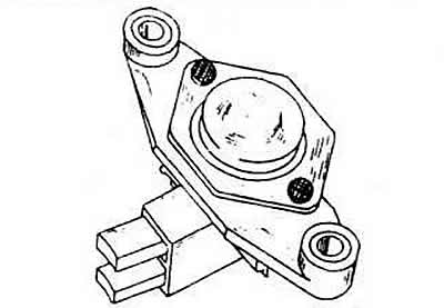
Checking the carbon brushes and brush traverse
Check the quality of contact between the carbon brushes and the slip rings. Check the mobility of the coals in the brush guides, if necessary, clean the brush holder with trichlorethylene.
If the protruding end of the brush has worn down to 5 mm, a new brush must be seasoned. Use a ruler to measure.
Rotor check
If slip rings become dirty or covered with grease, wipe them with a cloth soaked in trichlorethylene. If there are scratches, polish them with the finest sandpaper.
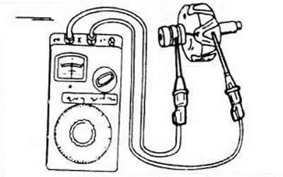
To test the insulation, place one ohmmeter test probe against the rotor core and the other against the slip rings. If the indicator does not show "endlessly" the rotor needs to be replaced.
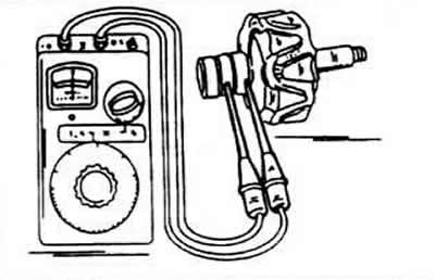
To check the flow of current through the rotor winding, carry both probes to the slip rings. The indicator should show 12.8-3.0 ohms. If the indicator shows «endlessly», the electrical circuit is open, otherwise there is a short circuit, if either of both faults, replace the rotor.
Stator check
Most often, in case of a short circuit, the location of the damage can be determined by external examination (it is very hot). Alternatively, one ohmmeter test probe can be placed against the collector ring and the other probe alternately applied to the four stator wires.
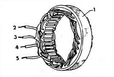
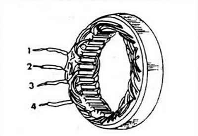
The instrument should show «endlessly». To check the current flow of the stator, connect four stator cables in pairs in turn. If the indicator reading does not match the specified value, the current flow is broken. The resistance value should be 0.10-0.11 ohms.
Diode control
It is possible to accurately control the consumption of the transmission voltage by the diodes and determine the reverse current only with the help of a special control device. This control must be carried out in the workshop.
Visitor comments