



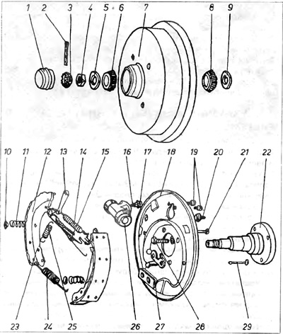
Figure 8.13. Rear drum brakes
1 - hub cap; 2 - check; 3 - crown protection; 4 - nut; 5 - spacer washer; 6 - outer bearing; 7 - brake drum; 8 - inner bearing; 9 - seal; 10 - spring plate; 11 - spring; 12 - brake shoe; 13 - self-regulating wedge; 14 - spring; 15 - spring; 16 - Air remover; 17 - Air bleeder cap; 18 - brake pad mounting disc; 19 - bolts securing the cylinder; 20 - rubber plug of the inspection hole; 21 - spring peg 11; 22 - rear hub axle; 23 - hole of the self-regulating spring; 24 - lower spring; 25 - self-regulating spring; 26 - brake cylinder; 27 - Brake shoe socket; 28 - fastening bolt; 29 - spring peg.
1. When starting to disassemble the drum brake, it is necessary to place wedges under the front wheels, loosen the rear wheel bolts, lift the rear of the car, place it on stands and remove the rear wheels.
2. Then lift it up with a screwdriver and remove the hub cap 1 (figure 8.13).
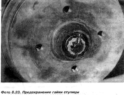
3. Straighten and remove the safety pin and safety ring (photo 8.23 and photo 8.24).
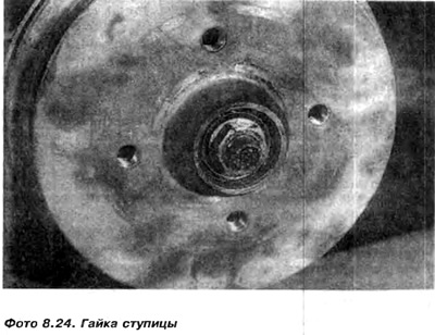
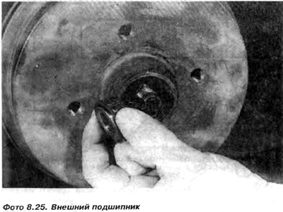
4. Unscrew the hub nut 4, remove the safety washer 5 and the outer bearing 6 (figure 8.13 and photo 8.25).
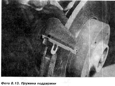
5. Check that the handbrake is completely released, and then remove the brake drum. If difficulties arise when removing the drum, it is necessary to first move the brake cheeks away from it by inserting a screwdriver through one of the holes left after the fastening bolts, the wheel to the drum and pushing the wedge of the self-adjuster upwards (photo 8.26).

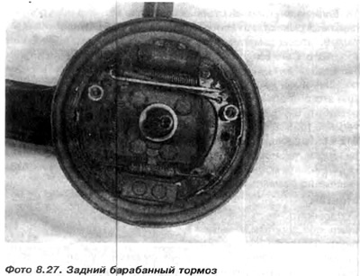
6. Clean the brake drum, cheeks and cheek mounting disc (photo 8.27).
7. Remove the guard from the plates 10 and take out the springs 11, pressing the cheeks to the disk 18. To do this, you need to grab the plates with pliers, press them towards the disk and turn them 90°. Sometimes a support for the wheel 21 is necessary so that it does not move back when pressing on the plate.
Remove plates 10, springs 11 and wheels 21 from the hole in the disk securing the cheeks (figure 8.13).
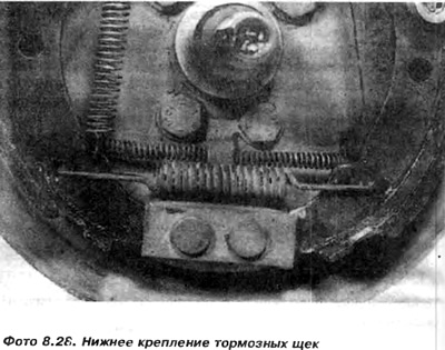
8. Mark the location of the cheek springs and the release bar. Then, lifting with a screwdriver, move and remove the lower ends of the cheeks from the socket 27 at the support pins. Father drink and remove the lower tightening spring 24.
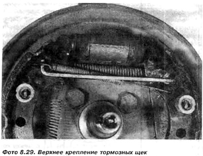
9. Remove the upper ends of the cheeks from the sockets in the brake cylinders. Unhook spring 25 of the wedge of the self-adjuster 13 and the upper tension spring 14, remove the cheeks (photo 8.29).
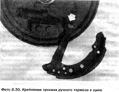
10. Disconnect the handbrake cable from the front brake cheek lever (photo 8.30).
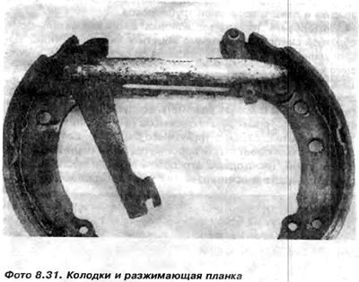
11. Secure the expansion bar in a vice and detach the cheeks, then remove the self-regulating wedge and spring (photo 8.31).
12. If brake fluid leaks from the cylinder are visible, the gaskets or the entire cylinder must be replaced. If only the gaskets are replaced, the cylinder must not be removed from the vehicle. It is only necessary to:
a) Clamp the flexible hose in front of the cylinder and unscrew the air bleeder using a hex key with a correspondingly deep socket for this purpose.
b) Place a flat container under the cylinder, lift the rubber covers and remove both pistons with the spring and gaskets.
c) Wash the piston and cylinder in alcohol, wipe dry. Check the working surfaces. If there are small scratches, you can try to sand them with 500 or 600 grit sandpaper. Wash and put the rubber covers on the piston, turning them outward.
d) Hold the piston with your fingers by the rubber covers and install new gaskets into the grooves on the pistons. Cover the polished surface of the piston with a thin layer of silicone grease. Insert the spring and pistons into the cylinder. Install the rubber cover into the grooves of the cylinder. The piston gaskets, previously lubricated with brake fluid, are inserted with the larger outer diameter into the middle of the cylinder.
13. If the working surfaces of the piston or cylinder are subject to severe corrosion or if the pistons are stuck in the cylinder, the cylinder must be replaced with a new one. This is done as follows:
a) Complete steps 12-12a.
b) Unscrew the brake pipe connection from the cylinder.
c) Unscrew the two bolts 19 securing the cylinder to the disk 18 and remove the cylinder (figure 8.13).
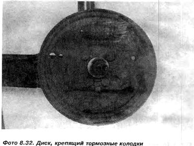
Note: If it becomes necessary to replace the disc securing the brake pads or the wheel hub axle, it is necessary to unscrew the four bolts from the suspension beam (photo 8.32).
d) Screw the new cylinder to the disk, loosen the air bleeder and press the brake pipe.
14. Install the brake pads in the reverse order of removal. It is necessary to ensure that the wedge projection of the self-adjuster is on the side of the disk securing the pads.
15. Remove the clamp from the flexible brake line. Wait until the fluid starts to flow out of the air bleeder hole and screw in the air bleeder.
16. Secure the handbrake cable (photo 8.30).
17. Check the condition of the brake drum. If the drum is scratched or has a clear threshold at the contact point with the shoes, it must be turned down. If after turning the drum diameter exceeds 181 mm, it must be replaced with a new one.
Note: Such components as brake shoes and drums cannot be replaced on one wheel, only on both at once. If replacement is performed on only one wheel, the car may skid to the side during braking.
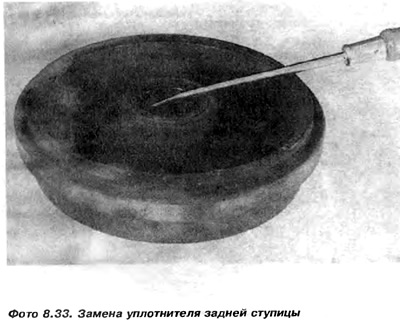
18. If traces of bearing grease are visible on the inside of the drum, this indicates that seal 9 is damaged. To replace the seal, lift it up with a screwdriver and remove it. Press a new one into its place (photo 8.33).
19. If you heard a loud noise from the bearings before disassembling the drum, you need to replace them with new ones. To do this, do the following:
a) Knock out the inner cone bearing 8 together with the seal 9 (figure 8.13).
b) Knock out the outer bearing tracks from the drum. Both for disassembly and for subsequent assembly of the track, it is necessary to use appropriate metal tubes and punches turned to size. Wash the hub.
Installation
c) Check if the bearing seats in the drum are clean. Then drive both tracks with the smaller diameter of the inner holes inward until they stop (figure 8 12).
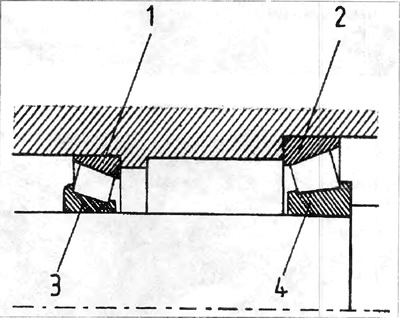
Figure 8.12. Laying the hub
1 - outer bearing track; 2 - inner bearing track; 3 - outer cone bearing; 4 - internal cone bearing.
d) Coat the inner bearing with grease and install it in the race. Grease the lip of the hub seal and drive it in flush with the edge of the hub.
d) Squeeze into the hub such a quantity of grease that it fills the entire space between the raceway rings up to the height of their inner edges.
20. After replacing the seal or bearings, the drum must be pushed onto the hub axle journal.
21. Lubricate the outer bearing and place it on the hub axle journal, pushing it toward the track. Then place the safety washer so that its tooth enters the groove, and tighten the nut to 20 Nm. Turn it several times to settle the bearings. Loosen the nut by half a turn and then slowly tighten it again. To check the bearing clearance more accurately, you can put the wheel on. After obtaining the normal clearance between the bearings and achieving easy rotation of the drum, stop tightening the nut.
22. Then you need to put the crown guard on the nut and install a new pin.
23. Fill the hub cap halfway with grease and lightly tap it into the hub hole
24. Lower the rear of the car and press the brake pedal several times to settle the pads.
25. If the brake pads have been replaced, the handbrake must be adjusted.
26. If the brake cylinder or linings are replaced, the system must be bled of air.
Visitor comments