



1. Remove the safety catch from the pin securing the servo pusher 15 to the pedal 17 (figure 8.2). The kingpin must be knocked out. Disconnect the pedal lever from the servo pusher in a similar manner.
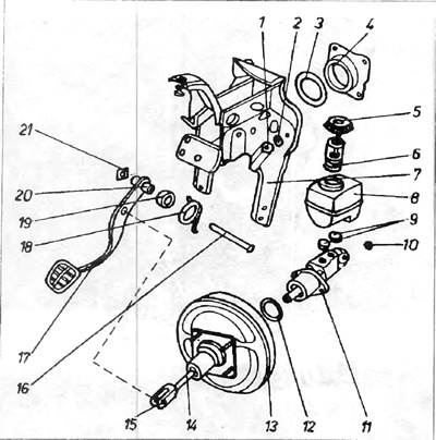
Figure 8.2. Elements of the braking system
1 - fastening nut; 2 - washer; 3 - gasket; 4 - servo bracket; 5 - fluid reservoir cap; 6 - liquid level sensor; 7 - pedal bracket; 8 - fluid reservoir; 9 - rubber gaskets; 10 - cylinder fastening nut; 11 - brake cylinder; 12 - gasket; 13 - servo; 14 - servo pusher; 15 - rod that attaches the pusher to the pedal; 15 - kingpin (pin); 17 - brake pedal; 18 - return spring; 19 - bushing; 20 - pedal rotation axis; 21 - kingpin protection.
2. Remove the safety catch 21 from the kingpin 16, unhook the spring 18 that lifts the brake pedal, knock out the kingpin and remove the pedal.
3. Check the condition of the working surfaces of the kingpin and pedal bushing. The kingpin must be cleaned and lubricated. When deep traces of wear are clearly visible on the surface, and before disassembly the pedal was dangling on the kingpin, the kingpin must be replaced with a new one. If after installing a new kingpin the gap is still large, then the bushing is worn out. It must be replaced.
Installation
4. Installation is performed in the reverse order of dismantling. It is important to remember that the surfaces of the bushing and kingpin must be lubricated.
[The article is published on this resource: www.vwmanual.ru]
Visitor comments