



1. Apply the handbrake, loosen the bolts securing the wheels. Raise the front of the car, place it on stands and remove both front wheels.
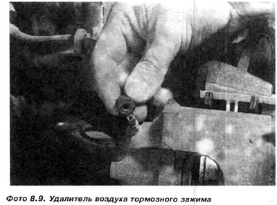
2. Clean the area around the air bleeder 4 and the flexible hose mount to the clamp. Unscrew the flexible hose from the clamp by half a turn and screw it back lightly. Remove the rubber cap from the air bleeder. Pour penetrating agent onto the air bleeder. It is also important that this agent gets inside the air bleeder opening (photo 8.9).
Caution: This operation is not performed unless there is a need to disconnect the clamp from the flexible hose during subsequent work.
3. Using a hex key, loosen the upper and lower bolts 1 and 9 with socket heads securing the clamp. Remove the bolts, paying attention to the location of the bushings 2 and 10 (photo 8.10).
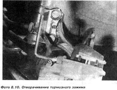
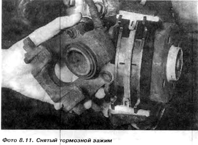
4. First pull out the lower part of the clamp, then the upper part. Hang the clamp so that its weight does not bend the elastic pipeline.
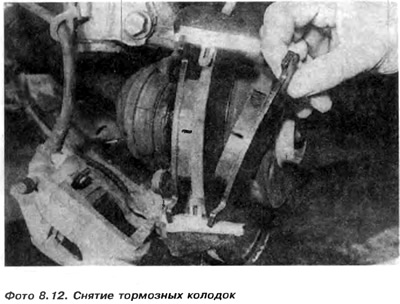
5. Remove pads 13 and 16 from the return mechanism, remembering that the pads are different from each other. The pad with the larger friction surface is attached from the inside.
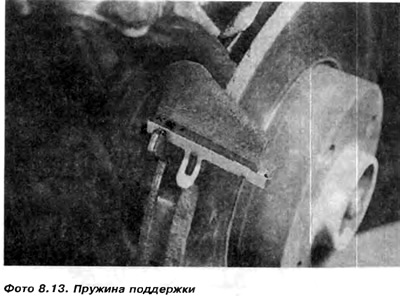
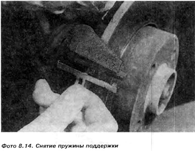
6. After removing the pads, you can remove the support springs (photo 8.13 and 8.14). These springs must be replaced if new pads are installed. Clean dirt from the return mechanism clamp with a wire brush and remove rust plates from the edge of the brake disc on the side of the pad mating plane. A sharp scraper is used for this. Resting it against the return mechanism, press the scraper tip to the disc surface and rotate it towards the scraper tip. The surface is leveled with sandpaper. If old pads are installed, it is necessary to clean rust from the surface where the pad meets the clamp bracket. The pads are replaced in both front brakes. Replacing the pads on one side may cause the risk of the car skidding to the side during braking, since the pads will have different rubbing surfaces. The old pads must be installed in their place.
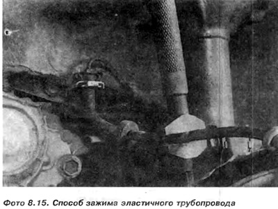
7. Clamp the elastic hose with a small French wrench with blunt edges to prevent brake fluid from leaking out after the clamp is loosened (photo 8.15).
8. Place a flat liquid tank under the clamp and unscrew the clamp from the pipeline. Plug the socket of the elastic pipeline in the removed clamp and clean it thoroughly.
9. Then secure the clamp in a vice and unscrew the air bleeder using a deep socket Allen key. Sometimes hitting the air bleeder from above with a hammer helps. If the air bleeder comes off during unscrewing, it can be drilled out, which can only be done by an experienced mechanic. Any damage to the threads or the conical sealing surface in the air bleeder socket is unacceptable.
When drilling out the air bleeder, use its internal hole to feed the drill. At the same time, it is necessary to control the depth of the drilled hole so as not to damage the sealed surface. If part of the thread is damaged, it is necessary to replace the clamp or drill out the hole and cut a new thread completely and of a larger diameter. A ball bearing of the appropriate diameter is inserted into the hole and pressed against the cone of the socket using a regular bolt. After such repair, it is necessary to check the tightness of the connection.
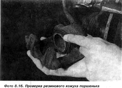
After unscrewing and removing the air bleeder, it is necessary to remove the rubber cover from the piston (photo 8.16).
10. Grasp the piston by the upper edge with pliers and, rotating it sideways, pull it out of the hole. If the piston does not come out, then the only way out is to screw the elastic hose back in, screw in the air bleeder and try to push the piston out by pumping the brake pedal.
Caution: Do not handle the piston with pliers by the polished surface.
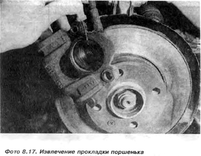
11. Remove the piston gasket from its seat inside the hole by lifting it with a screwdriver (photo 8.17).
The original article is posted on the website: VWmanual
12. Wash the piston and the clamp cylinder with alcohol and check their surfaces. If there are small traces of abrasion or corrosion, they can be sanded with 500 or 600 grit sandpaper. The piston is sanded along the perimeter, not along the scratches, through which fluid could leak under the gasket. In case of major damage, the piston and clamp must be replaced.
13. If the components are in good condition, it is enough to replace the gasket set. Before installing the piston gasket in the groove in the cylinder bore, it is necessary to dip it in brake fluid so that it lies evenly in the groove and is not damaged during the installation of the piston.
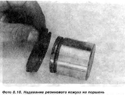
14. A new rubber casing must be put on the piston (photo 8.18 and 8.19). Cover it with a thin layer of silicone grease and carefully press it into the clamp hole (photo 8.23).
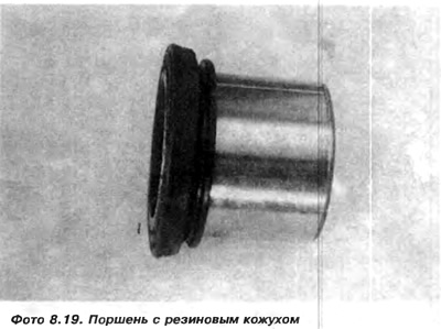
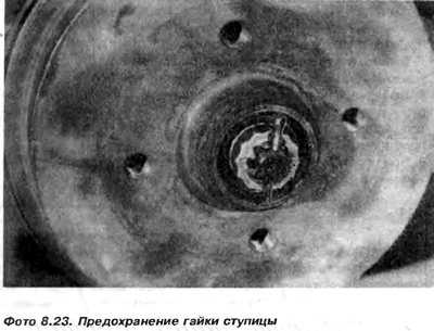
Insert the outer cuff of the rubber casing into the socket of the clamp body. Screw in the air bleeder.
15. Check that the end of the flexible pipeline is clean, then remove the plug from the clamp and screw it onto the pipeline, but do not tighten it.
16. Install the support springs and pads.
17. Install the clamp on the bracket by first installing the upper part of the clamp and rotating it downwards. Install the upper bolt first, then the lower one and tighten it to 40 Nm.
Caution: When installing and tightening, do not press hard on the clamp to avoid bending the pad support springs. Bent springs cause noise when braking.
18. Tighten the elastic hose connection so that it is not twisted and does not rub against other elements.
19. Loosen the clamping key from the flexible hose and remove air from the brake system.
13. It is usually sufficient to remove the air around the wheel where the clamp was removed.
Note: If you are only inspecting or replacing the brake pads, you must push the piston out several times by pumping the brake pedal and press it, for example, with a hammer handle, into the clamp. During this operation, the clamp should rest with its back against the return mechanism, not against the brake disc. To do this, push the piston in until it stops, then allow another person to push it out 15 mm while pressing the brake pedal and press it back.
If the stroke is greater than 15 mm, the piston may fall out of the clamp and it will be necessary to bleed the brakes. When using very strong force to push the piston in, rotate the piston around its axis, grasping the upper edge with pliers. Be careful not to damage the rubber boot. Then, using a flat block with a long bolt, push the piston in until it stops (photo 8.21).
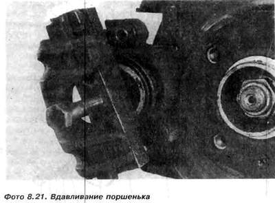
After installing the brake clamp, it is necessary to bleed the air from the brake system each time. If only the brake pads are replaced, it is necessary to press the brake pedal several times so that the pads move towards the disk to the appropriate distance. If this operation is not performed, the brake will not work at the first braking, since the pads are spread apart. It is necessary to always remember this. Check whether the resistance in the system is too high after installing the brake clamp and bleeding air during the rotation of the brake disk.
These calipers were used in older VW models. The gti versions are equipped with upgraded Girling type brake calipers with ventilated brake disc and ABS (figure 8.8).
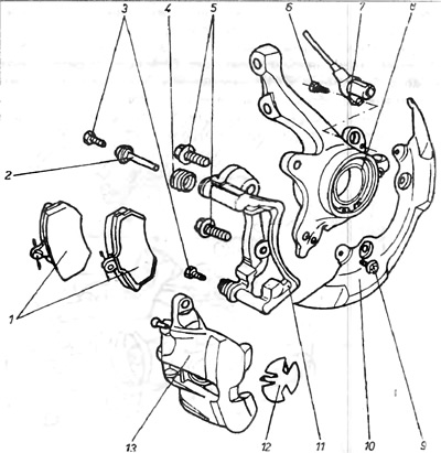
Figure 8.8. Front brake caliper type Girlihg
1 - brake pads; 2 - guide bushing; 3 - bolt; 4 - rubber casing; 5 - bolt; 6 - bolt; 7 - ABS sensor; 8 - return mechanism; 9 - bolt; 10 - brake disc casing; 11 - return mechanism holder; 12 - spring; 13 - brake clamp.
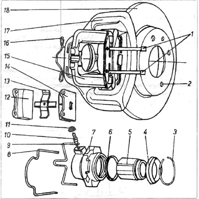
Figure 8.6. Texes type brake clamp
1 - fixing pegs; 2 - screw securing the disc to the hub; 3 - spring ring; 4 - rubber casing; 5 - piston; 6 - piston gasket; 7 - clamp cylinder; 8 - latch; 9 - latch; 10 - Air remover; 11 - air gel removal cap; 12 - brake shoe; 13 - repulsion spring; 14 - brake shoe; 15 - clamp frame; 16 - latch of fixing pegs; 18 - brake disc.
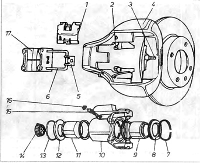
Figure 8.7. Girling brake clamp
1 - protection; 2 - locking latch; 3 - fixing bolt; 4 - clamp frame; 5 - fixing tin plate; 6 - fixing forks; 7 - spring ring; 8 - rubber casing; 9 - piston 10 - clamping cylinder; 11 - piston; 12 - rubber casing; 13 - spring ring; 14 - support; 15 - Air remover; 16 - rubber casing of air remover; 17 - brake pads.
Visitor comments