
1. Remove the brake cylinder as described in paragraph 5 of this section.
2. Disconnect the reduced pressure hose from the servo and, if necessary, the shut-off valve.
3. Remove the lower case of the dashboard on the driver's side.
4. Remove the protection from the king pin securing the servo pusher 15 and remove the king pin.
5. Unscrew the 4 nuts securing the servo housing to the bracket 7. Pull the servo out.
Installation
6. Installation is carried out in the reverse order to dismantling. Before installation, both kingpins must be coated with a small amount of grease. Defective servo nuts must be replaced with new ones.
7. Damage to the servo valve can cause so-called side air to be sucked into the intake manifold. This is determined by the change in engine idle speed after pressing the brake pedal. If damage is suspected, the valve must be replaced with a new one.
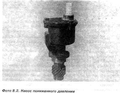
Reduced pressure pump
In diesel engines, there is no reduced pressure in the inlet manifold required for servo operation. Reduced pressure is created by a vacuum pump (photo 8.2). The vacuum pump is driven by an intermediate shaft with a vane (photo 8.3).
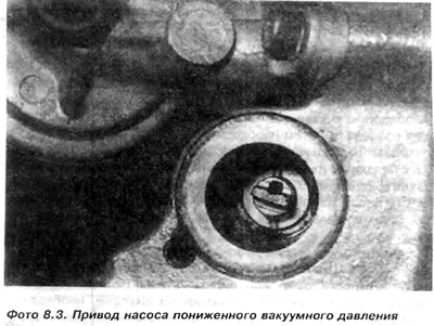
The drive fin is advanced from the axis of the shaft, therefore, during assembly, it is necessary to accurately position the cutout in the pump shaft in relation to the drive fin.
To check the operation of the vacuum pump, you must:
1. Remove the flexible tube from the pump connection.
2. Start the engine.
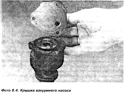
3. Cover the fitting hole. Check if a vacuum is formed. If the pump does not create a vacuum, you can remove the pump cover, indicating its position in relation to the housing (photo 8.4).
4. Checking the condition of the pump must be done at an authorized service station.
Visitor comments