



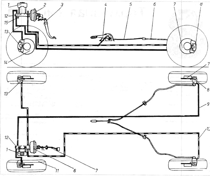
Figure 8.1. Brake system diagram
1 - brake fluid reservoir; 2 - hydrovacuum booster - servo; 3 - brake pedal; 4 - handbrake lever; 5 - handbrake cable; 6 - metal protection for handbrake cable; 7 - rear brake disc; 8 - rear brake caliper; 9, 10 - brake pipes; 11 - front wheel; 12 - brake cylinder 13 - front brake disc.
1. The main brake is controlled by pedal 3, which through the pusher and the hydraulic vacuum booster - servo 2 sets in motion the two-stage brake cylinder 12. In case of failure of one circuit, the second makes it possible to stop the car. The brake system is divided diagonally one front wheel - one rear wheel
2. Brake fluid reservoir 1 is secured to brake cylinder 12. It is equipped with a float-type brake fluid level sensor, which signals a very low brake fluid level.
3. The brake cylinder creates pressure, which is supplied to the front wheel chain through the brake lines (in the figure it is indicated by a solid line) and to the rear wheel chain (in the figure it is indicated by a dotted line).
4. The hydraulic vacuum booster (servo) 6 is fixed to the engine bulkhead wall and is connected to the engine intake manifold. The main elements of the servo are the diaphragm and the shut-off valve. When the engine is not running, the servo does not operate and effective braking requires a stronger pressure on the pedal. When the engine is running, the reduced pressure is supplied through the channels to both sides of the diaphragm. When the pedal 3 is pressed, the space on one side of the diaphragm is connected to the atmosphere. The resulting pressure difference provides additional force that compensates for the force applied by the driver when pressing the brake pedal, which provides greater braking efficiency of the car without the need for strong pressure on the brake pedal.
5. The brake force corrector, available in some versions of cars, reduces the fluid pressure in the rear wheel clamps depending on the deflection of the rear suspension. With a small deflection of the suspension, which occurs due to a small load on the rear axle, the rear brakes should work weaker. When the pressure on the rear axle increases, the braking force increases, which automatically corrects the braking force. During sharp braking, the rear part of the car body is slightly raised, causing a decrease in the load on the wheels of the rear axle. In cars without a corrector, during sharp braking, the rear wheels may lock, thereby reducing the braking efficiency. The corrector reduces the likelihood of skidding of the rear wheels, which significantly improves the stability of the car during braking, especially on slippery surfaces.
6. The expansion devices 13 press the brake shoes against the brake disc 14 via the pistons, causing the braking effect. If the brake pedal is released, the shoes move away from the disc each time by the same distance, regardless of wear. In this way, a constant gap is maintained between the discs of periodic clearance adjustment. In case of wear, the brake shoes must be replaced with new ones. In some versions, expansion devices are also located on the rear wheels,
7. The auxiliary brake (hand brake) acts only on the rear wheels. The tightening of the hand brake is transmitted by lever 4, which pulls cable 5. The cable sets the brake mechanisms of the rear wheels in motion. A switch is installed under the lever. which turns on a light on the dashboard signaling the tightening of the hand brake. The same light is connected to the circuit signaling a very low level of brake fluid in the reservoir 1 (figure 8.1).
Visitor comments