
English Русский
Български
Беларускі
Український
Српски
Hrvatski
Română
Polski
Slovenský
Magyar
  |  Articles  |  Sitemap  |  Contacts  |    |
Car maintenance Ford Car maintenance Hyundai Car maintenance Chevrolet Car maintenance BMW Car maintenance Audi Car maintenance Opel Car maintenance AvtoVAZ
VWmanual.ru


Main   Passat   Golf   Polo   Touareg   Tiguan   Sharan   Transporter   Others  
Golf 1 (1974-1984, diesel) Golf 1 (1974-1984, petrol) Golf 2 (1984-1993, petrol) Golf 2 (1984-1993) Golf 3 (1991-1997) Golf 4 (1997-2004) Golf 5 (2003-2008)

Rear wheel brake calipers (VW Golf 2)

  • Main
  • Golf
  • Golf 2
  • Chassis
  • Brake system
  • Rear wheel brake calipers
            0


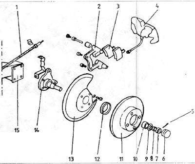
Some types of cars have disc brakes on the rear wheels. The brake calipers are removed as follows (figure 8.9).

Figure 8.9. Rear disc brake

1 - handbrake cable; 2 - clamp bracket; 3 - brake pads; 4 brake clamp; 5 - check; 6 - hub cap; 7 - crown protection; 8 - hub journal nut; 9 - washer; 10 - bearing; 11 - brake disc; 12 - seal housing; 13 - brake disc casing; 14 - hub axle; 15 - rear axle beam.


1. Block the front wheels with chocks. Loosen the bolts holding the wheels. Raise the rear of the car, place it on chocks and remove the two rear wheels.

2. Clean the area around the air bleeder and the flexible hose mount to the clamp. Unscrew the flexible hose from the clamp by half a turn and screw it back lightly. Remove the rubber cap from the air bleeder. Pour penetrating agent onto the air bleeder so that it gets inside the air bleeder opening.

Caution: The operations described in paragraph 10.2 must not be carried out if the clamp is not disconnected from the brake pipe during the subsequent steps.


3. Disconnect the handbrake cable 1 from the clamp (figure 8.9).
4. Loosen and remove the upper bolt. If you are only inspecting or replacing the brake pads, simply tilt the clamp forward, paying attention to its position on the lower bolt. Before removing the pads 3, mark their position so that after inspection and cleaning they are installed exactly in their place, on the same side of the disc. After removing the pads, clean both the working surfaces of the pads and the bracket of the clamp 2. To familiarize yourself with the notes regarding the installation of new pads and the clamp, go to point 10.17


5. Unscrew and remove the lower fastening bolt 3 and remove the clamp 5 (Fig. 8.10)

Note: Both bolts must be replaced with new ones during assembly.


6. Clamp the flexible pipeline with a small French wrench with blunt edges so that the brake fluid does not leak out after the clamp is unscrewed from the brake pipeline.

7. Place a flat liquid tank under the clamp, unscrew the clamp from the pipeline. Plug the socket of the elastic pipeline in the clamp and clean it thoroughly.

8. Secure the clamp in a vice and unscrew the air bleeder 2 with a strong Allen key with a deep socket. You can also hit the air bleeder from above with a hammer.

9. After unscrewing the air bleeder, it is necessary to remove the rubber cover 9 of the piston 8, lifting it with a screwdriver (figure 8.10).
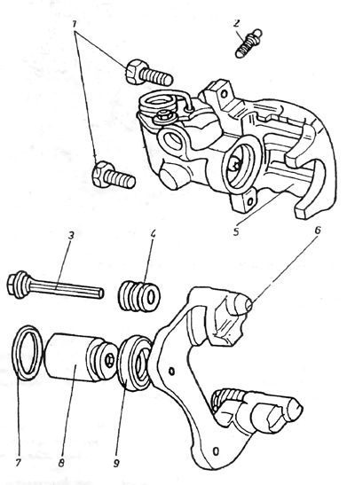
Figure 8.10. Rear brake caliper

1 - bolt securing the clamp bracket to the suspension beam; 2 - air remover; 3 - fastening bolt; 4 - bolt cover; 5 - rear brake caliper; 8 - clamp bracket; 7 - piston sealing ring; 8 - piston; 9 - piston casing.


10. Using a hex socket wrench, remove the piston from the rear clamp (figure 8.11).
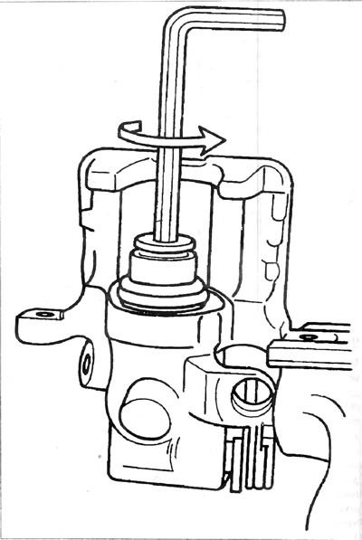

Figure 8.11. Unscrewing the rear clamp piston


11. Use a small screwdriver to remove the gasket from the groove in the cylinder (photo 8.17)

The information is presented on the website: www.VWManual.ru
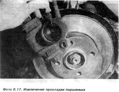
11. Use a small screwdriver to remove the gasket from the groove in the cylinder (photo 8.17)


12. Wash the piston and cylinder surfaces with alcohol and check their condition. If the traces of corrosion or abrasions are small, they can be sanded with 500 or 600 grit sandpaper. Sand the piston along the perimeter, not along the scratches, through which fluid could leak under the gasket. If there is significant damage to the surfaces, the piston or clamp must be replaced.

13. If the elements are in good condition, it is enough to replace the gasket 7 and the rubber casing 9. Before installing the gasket 7 of the piston 8, it is necessary to lower it into the brake fluid so that it lies evenly in the groove and is not damaged during the installation of the piston.

14. Put the rubber cover on the piston, turn it outwards and cover the piston surface with a thin layer of silicone grease. Then carefully screw it into the cylinder hole until it stops. Install the rubber cover 9 in the clamp seat.

15. Screw in the air bleeder with silicone grease. Before installing the clamp, it is necessary to pre-fill it with brake fluid to avoid problems with air bleeding. To do this, it is necessary to fix the clamp vertically. Put a plastic tube on the air bleeder and use a syringe to fill the clamp with fluid until it starts to flow out of the hole connecting the clamp to the elastic pipeline without bubbles. Screw in the air bleeder and plug the hole of the elastic pipeline.

16. Now you can install the clamp in the car. Install a new self-locking bolt in the lower hole and install the clamp. Then tighten the elastic tube. Remove the clamping key from the tube. Install the brake shoes, paying attention to the markings made during disassembly.

Caution: It is important that the clamp is secured with the piston installed in such a way that there is a gap of 1 mm between the pads and the clamp.


To do this, with the new lower bolt installed, turn the clamp and install it on the pads. Screw the old bolt into the upper hole and measure the gap with a feeler gauge. If the gap is incorrect, unscrew the upper bolt, tilt the clamp, adjust the position of the piston by rotating it to the sides. When the piston is correctly adjusted, it will be necessary to reinstall the clamp, insert the new bolt and tighten it with a torque of 40 Nm.

17. Install the handbrake cable. When replacing the pads, you must first loosen the cables at the handbrake lever, then connect the cable to the clamp lever and adjust the length of the cables.

18. Remove air from the brake system.

19. After installing the clamp, you need to put on the wheels and lower the car.

This article is available at russian, bulgarian, belarusian, ukrainian, serbian, croatian, romanian, polish, slovak, hungarian
The text has been checked: Semenova Anna

Share information:

Previous articles
Front brake disc
Front wheel brake calipers
Brake force corrector
Rigid and flexible brake lines
Brake cylinder
Servo
Next articles
Rear brake disc
Rear drum brakes
Bleeding the brake system
Handbrake lever
Brake system fault table


Similar articles from other manuals for VW cars:
Technical characteristics of the rear wheel brake mechanisms Passat B2 (1981-1988)
Front brakes with brake calipers «VW I» and «VW II» Polo 3 (1995-2003)
Repair of rear wheel brakes, brake caliper FN 44 Touareg 1 (2002-2006)
Repair of rear brake calipers Tiguan 1 (2007-2015)
Disassembly and assembly of the rear wheel brake mechanism Sharan 1 (1995-2000)
Disabling the rear wheel brake Transporter T3 (1979-1992)
Rear wheel brake — design description Beetle (1960-1986)
Link to this page in different formats


Visitor comments


No comments yet


How much will 31 + 35 =


Golf 5 
  • General information
  • User manual
  • Maintenance
  • Troubleshooting
  • Power unit
  • Engine repair
  • Cooling and ventilation system
  • Fuel system
  • Ignition system
  • Transmission
  • Clutch
  • Mechanical gearbox
  • Automatic gearbox
  • Chassis
  • Brake system
  • Car suspension
  • Steering
  • Body
  • Interior (internal elements)
  • Exterior (external elements)
  • Doors and covers
  • Electrical equipment
  • Power devices
  • Washers and wipers
  • Lighting and appliances
  • Electrical circuits
Golf 4 
  • General information
  • User manual
  • Weekly checks
  • Maintenance
  • Power unit
  • Petrol engines
  • Diesel engines
  • Cooling system
  • Fuel system (petrol)
  • Control system (petrol)
  • Fuel system (diesel)
  • Exhaust system
  • Transmission
  • Clutch
  • Car gearbox
  • Drive shafts
  • Chassis
  • Car suspension
  • Steering
  • Wheels and tires
  • Brake system
  • Body
  • Exterior (external elements)
  • Interior (internal elements)
  • Ventilation and heating
  • Car doors and sunroof
  • Washers and glass cleaners
  • Electrical equipment
  • Power devices
  • Lighting and appliances
  • Electrical circuits
Golf 3 
  • Petrol engine
  • Engine repair
  • Lubrication system
  • Cooling system
  • Ignition system
  • Diesel engine
  • Engine repair
  • Diesel injection system
  • Pre-glow system
  • Transmission
  • Clutch
  • Gearbox and drive shafts
  • Chassis
  • Steering
  • Wheels and suspension
  • Brake system
  • Electrical equipment
  • Lighting and appliances
  • Electrical circuits
Golf 2 
  • General information
  • Introduction to guide
  • User manual
  • Petrol engines 1.3 l
  • Engine repair
  • Lubrication system
  • Cooling system
  • Carburetors
  • Supply system
  • Ignition system
  • Petrol engines 1.6/1.8 l
  • Engine repair
  • Supply system
  • Ignition system
  • Diesel engines
  • Engine repair
  • Lubrication system
  • Cooling system
  • Power and exhaust system
  • Transmission
  • Clutch
  • 4-speed gearbox 084
  • 5-speed gearbox 085
  • 4-speed gearbox 020/4R
  • 5-speed gearbox 020/4T
  • Automatic gearbox
  • Drive shafts
  • Chassis
  • Steering
  • Car suspension
  • Brake system
  • Body
  • Body elements
  • Doors, locks and windows
  • Electrical equipment
  • Equipment and devices
  • Power devices
Golf 2 (petrol) 
  • General information
  • Characteristics
  • Car care
  • Maintenance
  • Power unit
  • Engine repair
  • Engine 1.05/1.30
  • Engine 1.60/1.80
  • Cooling and lubrication system
  • Power and exhaust system
  • Transmission
  • Clutch
  • Car gearbox
  • Drive shafts
  • Chassis
  • Brake system
  • Steering
  • Suspension
  • Body
  • Body and equipment
  • Electrical equipment
  • Lighting and appliances
  • Electrical circuits
Golf 1 (petrol) 
  • General information
  • Characteristics
  • User manual
  • Maintenance
  • Power unit
  • Engine adjustment
  • Engine 1.1/1.3
  • Engine 1.5/1.6/1.8
  • Engine electrical equipment
  • Cooling system
  • Fuel system
  • Transmission
  • Clutch and manual gearbox
  • Automatic gearbox
  • Chassis
  • Steering
  • Front suspension
  • Rear suspension
  • Brake system
  • Electrical equipment
  • Lighting and appliances
  • Electrical circuits
  • Body
  • Body and equipment
  • Optional equipment
Golf 1 (diesel) 
  • General information
  • Specifications
  • Maintenance
  • Power unit
  • Engine repair
  • Exhaust and turbocharger
  • Cooling system
  • Fuel system
  • Fuel injection system
  • Transmission
  • Clutch and drive shafts
  • Car gearbox
  • Chassis
  • Suspension and wheels
  • Steering
  • Brake system
  • Wheels and tires
  • Body
  • Heating and ventilation
  • Exterior (external elements)
  • Interior (internal elements)
  • Doors and windows
  • Electrical equipment
  • Equipment and devices
  • Lighting system
  • Power devices
  • Electrical circuits
VWmanual.ru © 2016-2026 | Mobile version | News and articles | Sitemap: EN BG BY UA RS HR RO PL SK HU | Write message | Site search
Passat B2 • Passat B3 • Passat B4 • Passat B5 • Passat B6 • Golf 1, diesel • Golf 1, petrol • Golf 2, petrol • Golf 2 • Golf 3 • Golf 4 • Golf 5 • Polo 3 • Polo 4 • Touareg 1 • Tiguan 1 • Sharan 1 • Transporter T3 • Transporter T4 • LT 28 • LT 2D • Beetle • Caddy 3 •
Our website uses cookies to ensure functionality and convenience.