

Crank mechanism: 1 - engine crankcase (clean and blow out the oil channels with compressed air, lubricate the adjacent surfaces with sealant); 2 - locating pin (pay attention to the installation density; 3 - camshaft bearing (lubricate with oil, install the ends in the recesses of the crankcase); 4 - 2nd main bearing (lubricate with oil, maintain installation position, do not rearrange); 5 - camshaft locking cover (install with sealant); 6 - pusher (lubricate with oil, secure with spring clips); 7 - camshaft; 8-1st main bearing (lubricate with oil; dowel pin hole faces flywheel); 9 crankshaft gear; 10 - main bearing (3 pcs.) (lubricate with oil; the hole for the dowel pin is directed towards the web of the crankshaft); 11 - bearing shell (maintain installation position, do not rearrange); 12 - ignition distributor drive gear (removed together with the crankshaft gear); 13 - crankshaft (clean, blow out oil passages with compressed air, do not install without corrosion protection); 14 - adjusting ring; 15 - retaining ring; 16 - 4th main bearing (lubricate with oil; the groove is directed towards the oil slinger disk); 17 - oil deflector disc (concave side - to the belt pulley); 18 - connecting rod; 19 - 35 Nm (3.5 kgcm) (lubricate adjacent surfaces with oil, connecting rod bolts (in a car with a 1200 engine) replace); 20 - connecting rod bushing
Disassembly
Remove engine (see section "Removal and installation of the engine").
Remove exhaust system (see section "Exhaust system replacement").
Remove intake manifold with carburetor (see section "Removal and installation of the carburetor").
Remove cooling fan (see chapter "Cooling system").
Remove oil cooler (see section "Removal and installation of an oil cooler").
Remove the ignition distributor and its drive shaft (see subsection "Removal and installation of the distributor of ignition").
Remove fuel pump (see section "Removal and installation of the fuel pump").
Remove V-belt pulley (see section "V-belt pulley replacement").
Remove the clutch (see section "Removal, check and installation of coupling").
Attention! When replacing the motor, pay particular attention to the installation instructions.
Remove flywheel (see section "Removal and installation of a flywheel").
Remove the oil filter with alternator bracket, oil pressure gauge and oil strainer (see chapter "Lubrication system").
Remove oil pump (see section "Removal, check and installation of the oil pump").
Remove cylinder head (see section "Removal and installation of cylinder heads").
Remove cylinders (see section "Removal and installation of cylinders").
Remove pistons (see section "Removal and installation of cylinders, pistons and piston rings").
Unscrew the nuts from the crankcase mounting studs with a socket wrench.
Rotate the crankcase so that the left half is at the bottom.
Secure with wire or spring clips the pushers in the right half of the crankcase.
Loosen the upper half of the crankcase with light blows of a rubber mallet and lift it up. In no case should a screwdriver or other auxiliary device be hammered into the joint to loosen it, otherwise the sealing surfaces will be damaged and the crankcase will become unusable. When lifting the right half of the crankcase, care must be taken that the connecting rods do not tip over to the side and do not damage the sealing surface of the left half of the crankcase.
Remove crankshaft and camshaft.
Attention! Mark the mounting position of the bearings to be separated. When removing the crankshaft and camshaft, make sure that all camshaft bearings and the 2nd crankshaft bearing are separated. Bearings can stick to the running surfaces of the shafts and be damaged when removed.
The camshaft bearings and the 2nd crankshaft bearing should only be removed after they have all been marked.
Remove the 6 O-rings from the studs on the 3rd bearing.
Remove the valve lifters.
Remove the safety valve of the lubrication system (see section "Removal and installation of the safety valve").
Examination
Use kerosene to clean the sealing surfaces of both halves of the crankcase from the remnants of the gasket, being careful not to damage the metal surface.
Carefully check the crankcase halves for damage and scratches.
Check studs for firm seating. Helix threaded inserts can be screwed into holes with worn threads.
Fasten both halves of the crankcase together without the use of sealant. Observe the prescribed tightening torques: 17 mm wrench - 35 Nm (3.5 kgcm), wrench 13 mm - 20 Nm (2.0 kgcm).
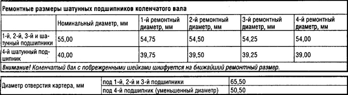
Check the diameters of the holes in the crankcase for the crankshaft bearings with a caliper and micrometer.
| Hole in crankcase | Diameter, mm |
| for 1st, 2nd and 3rd bearings | 65,00 |
| for 4th bearing | 50,00 |
Attention! The engine installed in place of the replaced one may differ from the last one by additional processing of various parts. By additional processing, it is possible to obtain increased or reduced installation dimensions compared to the nominal. A crankcase with an additionally machined aligned joint surface or with holes for an increased size of the crankshaft bearings is marked on the end side of the right half of the crankcase (near the interface) letters "R" or "ABOUT". Engines marked with a letter "ABOUT", have oversized V-belt pulleys. These pulleys are marked with two circular grooves on the front side. In the case of refinished cylinder seats, compensating washers are installed between the crankcase and the cylinder head gasket. The installation of compensating rings must not be neglected, otherwise the compression in the engine cylinders will change.
Assembly
Attention! Both halves of the crankcase are processed as an assembly during manufacture. Therefore, they should also be replaced together.
Thoroughly wash both halves of the crankcase in kerosene and blow out the oil passages with compressed air.
Raise the left half of the crankcase.
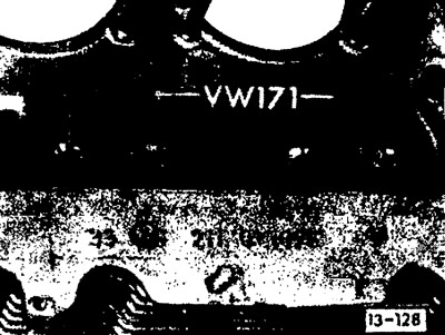
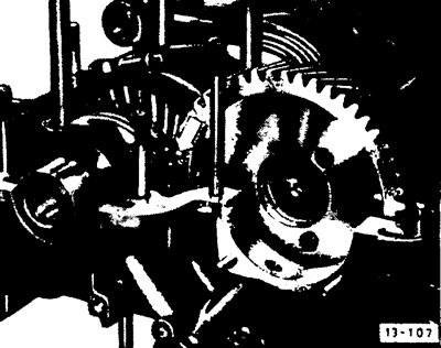
The crankshaft and camshaft are installed correctly if the mark on the camshaft is located between the marks (see arrow) crankshaft gears.
Lubricate the crankshaft and camshaft bearing shells with oil and install the bearing shells according to the marks.
Install the crankshaft and camshaft, observing the markings.
Put 6 new O-rings on the studs.
Coat mating surfaces of crankcase halves evenly with a thin coat of Curil sealant. The sealant must not get into the oil channels of the crankshaft and camshaft bearings.
Insert the oiled tappets into the right half of the crankcase and secure them with spring clips or wire.
Install the camshaft locking cover with the bottom of the cover out, lubricating it with sealant.
Connect the crankcase halves.
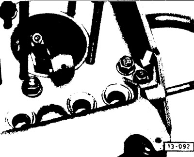
First tighten the M8 nut to 20 Nm (see arrow), located next to the M12 stud of the 1st crankshaft bearing. Then tighten the M12 nuts to 35 Nm. Then tighten all remaining M8 nuts to 20 Nm.
Attention! Follow the specified order for tightening the nuts.
Check the ease of rotation of the crankshaft.
Assemble the engine in the reverse order of disassembly.
Visitor comments