
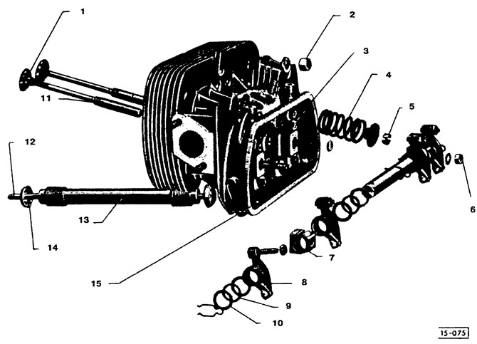
Cylinder head: 1 - valve; 2 - nut (tightening torque for M10 stud - 30 Nm (3.0 kgcm), for M8 stud - 25 Nm (2.5 kgcm)). Follow the tightening sequence; 3 - cuff of the valve stem (replace for intake valves only); 4 - valve spring (end with a smaller pitch - to the cylinder head); 5 - valve crackers (adjust with increased thermal gap); 6 - hex nut M8 (covered with copper; tightening torque 25 Nm (2.5 kgcm)); 7 - support (installed upside down); 8 - valve rocker (check for wear); 9 - spring washer; 10 - thrust washer; 11 - valve guide sleeve; 12 - push rod (check for bending between two base elements; runout - max. 0.3 mm); 13 - protective tube (pre-tension - seam up); 14 - sealing ring (replace); 15 - cylinder head
Attention! In the event that only the protective tube of the valve lifter is damaged or it becomes necessary to replace the sealing ring of the tube, there is no need to remove the cylinder head, because. there are detachable protective tubes.
Removing
Remove engine (see section "Removal and installation of the engine").
Remove intake manifold with carburetor (see section "Removal and installation of the carburetor").
Remove fan.
Remove muffler (see chapter "Exhaust system").
Remove engine covers.
Flush the engine with petrol, especially in the area of the cylinder heads.
Attention! Avoid open flames as there is a risk of fire!
Bend down the cover retaining bracket with a large screwdriver.
Remove cover (rinse before installation).
Unscrew the 2 M8 hex nuts securing the valve rocker shaft.
Remove the axle together with the rocker arms. Remove the O-rings under both support legs (when installing, replace them with new ones).
Remove push rods.
Loosen 8 bolts (location see subsection "Installation") and remove them together with washers.
Attention! If it is necessary to remove only the cylinder head without removing the cylinder and piston, then the cylinder must be secured against falling out with suitable wire loops or a tin clamp.
Note. To facilitate the removal of the cylinder head in this case, you can use a rubber mallet.
Remove the cylinder head and valve lifter protection tube.
Installation
Attention! When installing heads with modified cylinder mounts, compensating rings 1 mm thick are installed between the cylinder and the head.
Before assembly, check the head for cracks in the combustion chambers and exhaust passages. Also check the sealing surfaces of the cylinder bases and the intake manifold flange. Replace damaged head.
Check spark plug threads and studs for damage. Damaged or stripped spark plug threads can be repaired with a wire helix thread insert.
When disassembling the rocker axles, check all parts for wear. Replace damaged parts and assemble according to the pictures.
Check the valve lifter rods for bending (runout should not exceed 0.3 mm). To do this, the bar is placed on a flat surface (e.g. on glass) and check the runout with a flat feeler gauge.
If scratches are found on the working surfaces of the rocker arms and bearings, they can be removed with fine-grained sandpaper. For this purpose, sandpaper is placed on a flat surface.
Before installation, pull out the old protective tubes of the pushers to the nominal size.
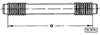
The protective tubes of the pushers are preloaded. Size "A" is about 180 mm for the engine of Kafer 1200 cars, and about 190 mm for Kafer 1300 cars.
Carefully install the cylinder head. When installing the pusher protective tube, make sure that the O-rings are properly seated between the crankcase and the protective tube, as well as between the latter and the cylinder head.
Attention! Use new O-rings for pusher protection tubes.
Unfold the protective tubes of the pushers so that the seam is directed upwards.
Place washers under cylinder head bolts and hand tighten.
Note. Bolts under the head cover (1, 2, 3, 4) install after lubricating with D3 sealant.
Attention! Use a torque wrench to tighten the cylinder head bolts.
Lightly tighten the cylinder head bolts in sequence to 10 Nm (1 kgcm).
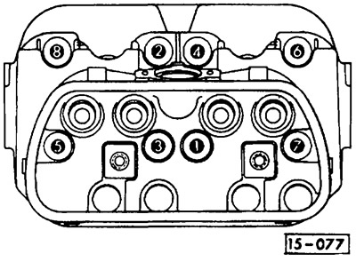
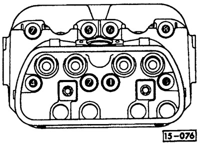
Finally tighten the cylinder head bolts in the sequence shown in the figure. M8 bolts are tightened with a torque of 25 Nm (2.5 kgcm), and M10 bolts - with a torque of 30 Nm (3.0 kgcm).
Insert the push rods, put new O-rings on both studs and install the valve lever axles on the studs.
Attention! Make sure that the cuts on the support legs (indicated by arrows) were on top, and their bevelled edges were directed outward.
Attention! Use only new hex nuts (M8). Tighten them with a torque of 25 Nm (2.5 kgcm).
Adjust valve clearances (see section "Valve clearance adjustment").
Install the valve cover with a new gasket.
Install engine covers and cooling fan.
Install muffler.
Install intake manifold and carburetor.
Install the engine.
Carry out a test drive and check that there are no oil leaks from under the valve covers.
Visitor comments