
English Русский
Български
Беларускі
Український
Српски
Hrvatski
Română
Polski
Slovenský
Magyar
  |  Articles  |  Sitemap  |  Contacts  |    |
Car maintenance Ford Car maintenance Hyundai Car maintenance Chevrolet Car maintenance BMW Car maintenance Audi Car maintenance Opel Car maintenance AvtoVAZ
VWmanual.ru


Main   Passat   Golf   Polo   Touareg   Tiguan   Sharan   Transporter   Others  
Passat B2 (1981-1988) Passat B3 (1988-1993) Passat B4 (1988-1996) Passat B5 (1996-2005) Passat B6 (2005-2010)

Removal and installation of the pump-injector (VW Passat B6)

  • Main
  • Passat
  • Passat B6
  • Diesel engine 2.0L
  • Fuel and exhaust systems
  • Removal and installation of the pump-injector
            0


Contents: Removal ↓ Installation ↓
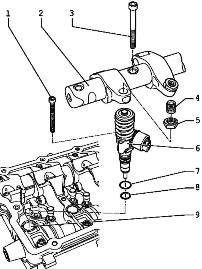
Fig. 2.363. Components of the pump-injector: 1 – bolt 3 Nm + 90° (1/4 rev.) + 180° (1/2 rev.); 2 –…

Fig. 2.363. Components of the pump-injector: 1 – bolt 3 Nm + 90° (1/4 rev.) + 180° (1/2 rev.); 2 – roller lever axis; 3 – bolt 20 Nm + tighten 1/4 turn. (90°); 4 – adjusting screw; 5 – lock nut; 6 – pump-injector; 7 – O-ring round section; 8 – O-ring round section; 9 – cylinder head


Removal


Remove the upper part of the timing belt cover and the cylinder head cover.

Loosen the locknuts of the adjusting screws and unscrew the adjusting screws until the corresponding rocker rests on the spring of the pump-injector pusher.
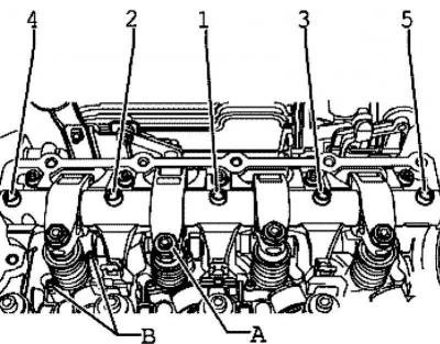
Fig. 2.316. Adjusting screw locknuts

Fig. 2.316. Adjusting screw locknuts


Loosen the 5-1 roller lever axle mounting bolts from outer to inner using a socket and remove the roller lever axle (fig. 2.316).


Remove the cable connection of the pump injectors and glow plugs.

Loosen the mounting bolts of the unit injectors using a nozzle and remove the bolts.

Remove the ball head bolt from the unit injector.
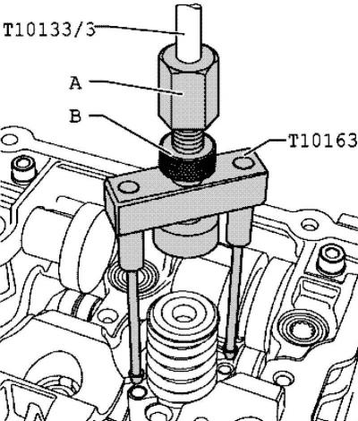
Fig. 2.364. Installing the puller into the bolt hole of the unit injector

Fig. 2.364. Installing the puller into the bolt hole of the unit injector


Install the puller into the bolt holes of the unit injector (fig. 2.364).

Gently rotate axis A away from the pump-injector. Tighten lock nut B by hand.

Using a hammer, tap the unit injector upwards from its seat on the cylinder head.

Note: Do not interchange previously used unit injectors.


Installation


The pump injector mounting screws must be replaced in any case.

Attention: When performing any work related to adjusting the pump-injector using the adjusting screw, it is necessary to replace the adjusting screw in the rocker arm and the screw with the ball head of the pump-injector, otherwise increased wear of these parts will occur.


Before installing the pump-injector, check that the new sealing rings are seated correctly.

Note: New unit injectors are supplied complete with O-rings.


Note: When installing an old unit injector, the sealing rings must be replaced.


Note: The sealing rings must not be twisted.


Note: Lubricate the O-rings and the stem of the unit injector with oil.


Note: Check the seat under the pump-injector in the cylinder head for contamination (for example, shavings, soot, etc.), clean with compressed air if necessary.


Very carefully insert the pump injector into the seat on the cylinder head.
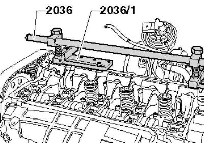
Fig. 2.365. Installing the mounting device

Fig. 2.365. Installing the mounting device


Install the mounting device with 2036/1, as shown in Figure 2.365, on the cylinder head support frame.

Caution: If the unit injector is overtightened with the mounting screws, there is a risk of it becoming skewed. This may result in poor driving performance and problems with starting the engine. Therefore, the unit injector should first be pressed into the seat and only then screwed on.
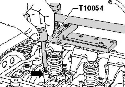

Fig. 2.366. Installing the mounting screw

Fig. 2.366. Installing the mounting screw


Insert new mounting screws and tighten them by hand without applying force until they stop (fig. 2.366).

Insert the valve puller with the mandrel.
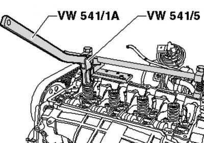
Fig. 2.367. Installing the pump-injector

Fig. 2.367. Installing the pump-injector


Press the pump-injector into its seat using a valve puller and hold it in this position (fig. 2.367).

Tighten the pump injector mounting screws by hand without applying force, using an insert until they stop.

Tighten the new mounting screws as follows:
  • stage 1 - 3 Nm;
  • stage II - 90° (1/4 turn);
  • stage III - 180° (1/2 turn).

Note: Replace the adjusting screws A and the ball head bolt of the unit injector.


Install the roller lever axle and tighten the new fasteners evenly in sequence 1–5 by hand (fig. 2.316).

Then tighten evenly in the same sequence with 20 Nm + turn by 90° (1/4 turn).

View the original on the website: VWmanual
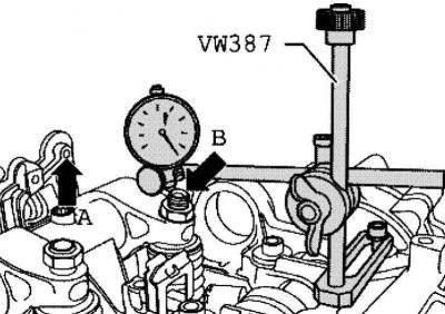
Fig. 2.368. Installing a pressure gauge on the adjusting screw of the pump-injector

Fig. 2.368. Installing a pressure gauge on the adjusting screw of the pump-injector


Install the micrometer as shown in Figure 2.368 on the adjusting screw of the unit injector.

Rotate the crankshaft in the direction of engine rotation until the rocker roller is at its highest point. Roller side A is at its highest point. Indicator B is at its lowest point

Remove the micrometer.

Then screw the adjusting screw into the rocker arm until you feel a noticeable resistance (the pump-injector is screwed in all the way).
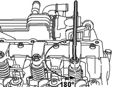
Fig. 2.369. Loosening the adjusting screw.

Fig. 2.369. Loosening the adjusting screw.


Turn the adjusting screw from the "tightened to the stop" position by 180° (fig. 2.369).

Hold the adjusting screw in this position and tighten the lock nut to 30 Nm.

Install the pump-injector plug and install the cylinder head cover and timing belt cover.

This article is available at russian, bulgarian, belarusian, ukrainian, serbian, croatian, romanian, polish, slovak, hungarian
The text has been checked: Orlov Dmitry

Share information:

Previous articles
Removal and installation the cable connection of pump-injectors and glow plugs
Safety precautions when repairing the direct fuel injection system
Installation of hose connections with nipple connectors of the supercharging system
Removal the fuel tank
Removal and installation the fuel level sensor
Removal and installation the fuel supply module
Next articles
Replacing the O-rings of the pump-injector
Free installation of the exhaust system
Exhaust gas recirculation system
Checking glow plugs
Removal, installation, inspection of ceramic glow plugs


Similar articles from other manuals for VW cars:
Fuel injection system (injector engine) Golf 1 (1974-1984, petrol)
Checking the fuel pump Polo 3 (1995-2003)
Checking and adjusting the position of the pump-injector pistons… Touareg 1 (2002-2006)
Removal and installation the cooling system pump Tiguan 1 (2007-2015)
Removal and installation the oil pump Sharan 1 (1995-2000)
Windshield Washer Water Pump — Checking and Replacing Transporter T4 (1990-2003)
Camshaft, valves and pump-injector drive Caddy 3 (2003-2010)
Link to this page in different formats


Visitor comments


No comments yet


How much will 10 + 38 =


Passat B6 
  • General information
  • User manual
  • Maintenance
  • Petrol engine 1.6L
  • Engine repair
  • Cooling and lubrication system
  • Fuel injection system
  • Petrol engine 2.0L
  • Engine repair
  • Lubrication system
  • Cooling system
  • Fuel and exhaust systems
  • Diesel engine 2.0L
  • Engine repair
  • Cooling and lubrication system
  • Fuel and exhaust systems
  • Transmission
  • Clutch
  • Mechanical gearbox
  • Automatic gearbox
  • Drive shafts
  • Chassis
  • Wheels and tires
  • Car suspension
  • Steering
  • Brake system
  • Body
  • Exterior (external elements)
  • Electrical equipment
  • Power devices
  • Lighting and appliances
  • Electrical circuits
Passat B5 
  • General information
  • User manual
  • Weekly checks
  • Maintenance
  • Power unit
  • Engine repair
  • Cooling system
  • Fuel system (petrol)
  • Fuel system (diesel)
  • Engine management
  • Exhaust system
  • Transmission
  • Clutch
  • Car gearbox
  • Drive shafts
  • Chassis
  • Car suspension
  • Wheels and tires
  • Steering
  • Brake system
  • Body
  • Exterior (external elements)
  • Interior (internal elements)
  • Doors and covers
  • Ventilation and heating
  • Electrical equipment
  • Power devices
  • Lighting and appliances
  • Electrical circuits
Passat B4 
  • General information
  • User manual
  • Maintenance
  • Technical data
  • 8-valve engine
  • Engine repair
  • Cooling and lubrication system
  • Supply system
  • Ignition system
  • Fuel injection «Mono-Jetronic»
  • Control system «Mono-Motronic»
  • Control system «Digifant»
  • Control system «Simos»
  • 16-valve engine
  • Engine repair
  • Cooling and lubrication system
  • Fuel injection «K-Jetronic»
  • Control system «KE-Motronic»
  • Control system «Digifant»
  • Diesel engine
  • Engine repair
  • Cooling and lubrication system
  • Power and control system
  • Turbocharging system
  • Digital control system
  • Transmission
  • Clutch
  • Manual gearbox
  • Hydromechanical gearbox
  • Front wheel drive
  • Chassis
  • Car suspension
  • Steering
  • Brake system
  • Body
  • Body elements
  • Electrical equipment
  • Power devices
  • Lighting and appliances
  • Electrical circuits
Passat B3 
  • General information
  • User manual
  • Driving Tips
  • Maintenance instructions
  • Technical data
  • Power unit
  • Engine repair
  • Ignition system
  • Lubrication system
  • Cooling system
  • Supply system
  • Petrol injection system
  • Diesel engine
  • Exhaust system
  • Transmission
  • Clutch
  • Car gearbox
  • Chassis
  • Suspension
  • Steering
  • Brake system
  • Wheels and tires
  • Body
  • Exterior
  • Interior
  • Heating system
  • Electrical equipment
  • Power devices
  • Lighting system
  • Equipment and devices
  • Wiper system
  • Electrical circuits
Passat B2 
  • General information
  • Introduction to instructions
  • User manual
  • Power unit
  • Engines 4-cylinder FZ
  • Engines 4-cylinder
  • Engines 5-cylinder
  • Transmission
  • Clutch
  • Four-speed gearbox
  • Five-speed gearbox
  • Hydromechanical gearbox
  • Front wheel drive
  • Chassis
  • Front suspension
  • Rear suspension
  • Steering
  • Brake system
  • Body
  • Body elements
  • Electrical equipment
  • Equipment and devices
  • Electrical circuits
VWmanual.ru © 2016-2026 | Mobile version | News and articles | Sitemap: EN BG BY UA RS HR RO PL SK HU | Write message | Site search
Passat B2 • Passat B3 • Passat B4 • Passat B5 • Passat B6 • Golf 1, diesel • Golf 1, petrol • Golf 2, petrol • Golf 2 • Golf 3 • Golf 4 • Golf 5 • Polo 3 • Polo 4 • Touareg 1 • Tiguan 1 • Sharan 1 • Transporter T3 • Transporter T4 • LT 28 • LT 2D • Beetle • Caddy 3 •
Our website uses cookies to ensure functionality and convenience.