



Contents: Installing a fuel tank ↓ Tightening torques ↓
Note: To remove the fuel tank, the rear axle must be lowered.
If necessary, pump fuel out of the tank using a fuel pump.
Remove the rear seats.
Remove the fuel delivery module cover.
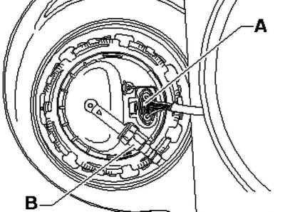
Fig. 2.205. Plug and fuel line
Disconnect the 5-pin plug from the flange (fig. 2.205).
Note: In vehicles with additional heating, the plug must also be disconnected from the metering pump.
Disconnect the plug connection of the all-wheel drive control unit.
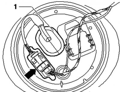
Fig. 2.344. Sealing sleeve
Release the sealing bushing 1 downwards from the cover and remove the wiring harness of the all-wheel drive control unit downwards (fig. 2.344).
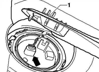
Fig. 2.345. Cover of 3-pin connector plug
Remove cover 1 and disconnect the 3-pin connector from the flange (fig. 2.345).
Remove the right rear wheel.
Remove the rear right fender liner.
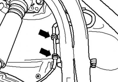
Fig. 2.346. Fastening the electric wire
Unlock the electrical wire from the filler neck (fig. 2.346).
Remove the fuel tank filler door assembly mounting bolt and remove the assembly completely.
Unscrew the fuel tank filler neck from the body.
Remove the left and right bottom trim.
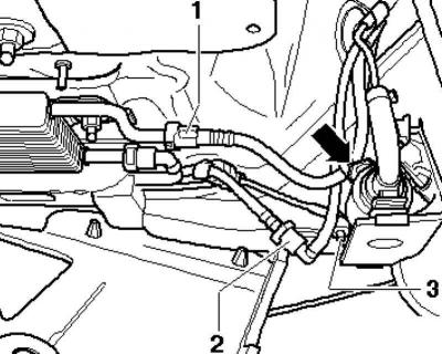
Fig. 2.347. Return and supply fuel lines
Disconnect the fuel return line 1 and the fuel supply line 2 from the connection points (fig. 2.347).
Disconnect the plug from the dosing pump.
Remove the cross support from the bottom.
Remove the protective shields under the propeller shaft.
Remove the rear propeller shaft pipe.
Remove the protective shield under the fuel tank.
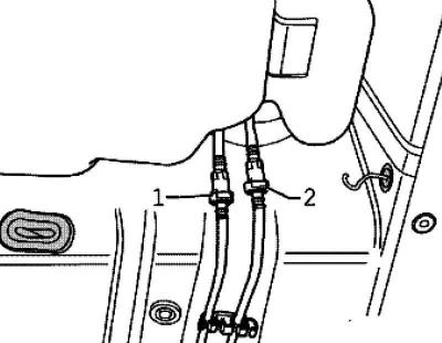
Fig. 2.348. White and black fuel lines
Disconnect the air line (white) 1 and the fuel line (black) 2 at the junction (fig. 2.348).
Note: To disconnect the fuel line, press the retaining ring.
Note: On vehicles with additional heating, it is also necessary to disconnect the fuel line of the metering pump
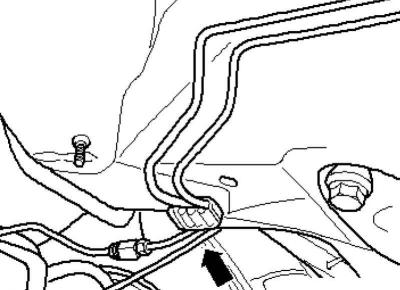
Fig. 2.349. Brake line holder
Unblock the brake lines on the left side of the body (fig. 2.349).
Support the rear axle on an engine and transmission stand.
Loosen the mounting bolts and lower the rear axle.
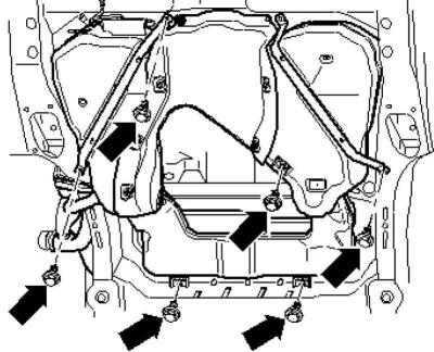
Fig. 2.350. Fastening bolts of stretchers and fuel tank
Remove the bolts securing the struts and fuel tank (fig. 2.350).
Support the fuel tank on the engine and gearbox stand in advance.
Slowly lower the fuel tank and at the same time unlock the wire to the 4WD control unit from the fuel tank.
Note: The filler neck must be "passed" between the body and the rear axle. To do this, lift the fuel tank with an assistant from the engine and gearbox stand.
Installing a fuel tank
With the help of an assistant, pass the filler neck between the rear axle and the body. Place the fuel tank on the engine and gearbox stand.
Block the AWD control unit wire on the fuel tank.
Slowly lift the fuel tank to the mounting position and secure it.
Reattach the rear axle to the body.
Further installation is carried out in the reverse order. In this case, the following must be taken into account.
Observe the installation position of the covers.
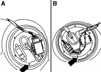
Fig. 2.351. Arrows for mounting position of covers
Arrows on the lids must point in the direction of travel (fig. 2.351).
A – Fuel delivery module cover.
B – Fuel level sensor cover 2.
Route the fuel and ventilation hoses without kinking them.
Check the reliability of the connections.
Check the ground connection between the tank and the body at the filler neck.
Tightening torques
Fuel tank to body: 25 Nm
Cross support to the bottom: 23 Nm.
Filler neck to body: 10 Nm
Visitor comments