



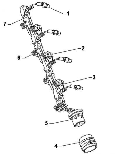
Pic. 2.356. Cable duct for pump injectors and glow plugs: 1 - glow plug plug; 2 - brackets made of stainless steel; 3 - fixing bolt; 4 – adapter ring; 5 – central plug; 6 - plug connection; 7 - cable channel
Removing
Remove the engine cover.
Attention: Assembly/disassembly of the cable connection is possible only after unscrewing/tightening the fixing brackets. When removing the cable channel from the brackets, these brackets are unbent, and too large a gap can lead to a cable break. This applies to work on replacing unit injectors, as well as to all types of work for which it is not necessary to completely disconnect the central plug.
Note: For piezoelectric injectors, the plug connection must only be removed with a puller.
Remove the cylinder head cover.
Disconnect the central connector on the cylinder head.
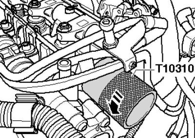
Pic. 2.357. Installing the key on the adapter ring
Place the key on the adapter ring and turn 90° (1/4 vol.) in the direction of the arrow (pic. 2.357).
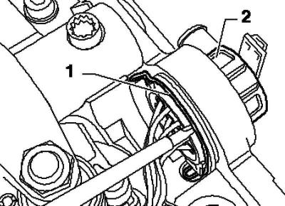
Pic. 2.358. Locking bracket and center plug
Pull the retaining clip 1 up slightly with a screwdriver and press the central plug inwards 2.
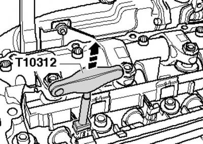
Pic. 2.359. Puller installation
Place the puller on the side of the plug-in connections of the unit injectors and remove them in the direction of the arrow (pic. 2.359).
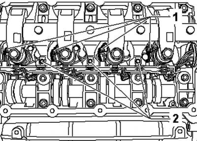
Pic. 2.360. Fixing bolts for glow plugs
Remove the plugs from the glow plugs 1. Unscrew the fastening bolts of the 2 stainless steel brackets and completely remove the cable connection (pic. 2.360).
Installation
Installation is carried out in the reverse order, taking into account the following.
Install the cable connection and tighten the fixing bolts with a torque of 10 Nm.
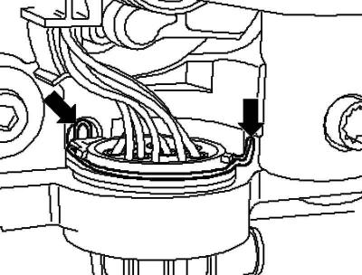
Pic. 2.361. Locking brackets
Install the center plug through the hole in the support module, making sure that the locking brackets are correctly installed (pic. 2.361).
Install the adapter ring (colored «long» mark indicates 12 o'clock).
Place the key on the adapter ring and lock by turning 90° (1/4 vol.) against the direction of the arrow.
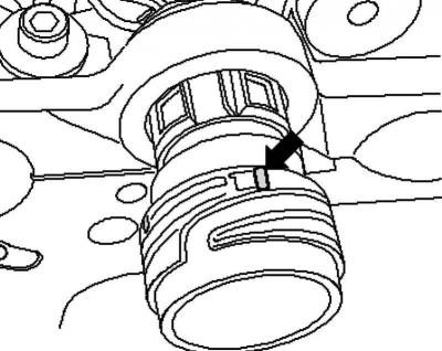
Pic. 2.362. Colored label for adapter ring
Note: When the adapter ring is correctly mounted, the colored «short» the marker will point to 12 o'clock.
Install and secure the central plug connection on the cylinder head (pic. 2.357).
Install the cylinder head cover.
Install the engine cover.
Visitor comments