



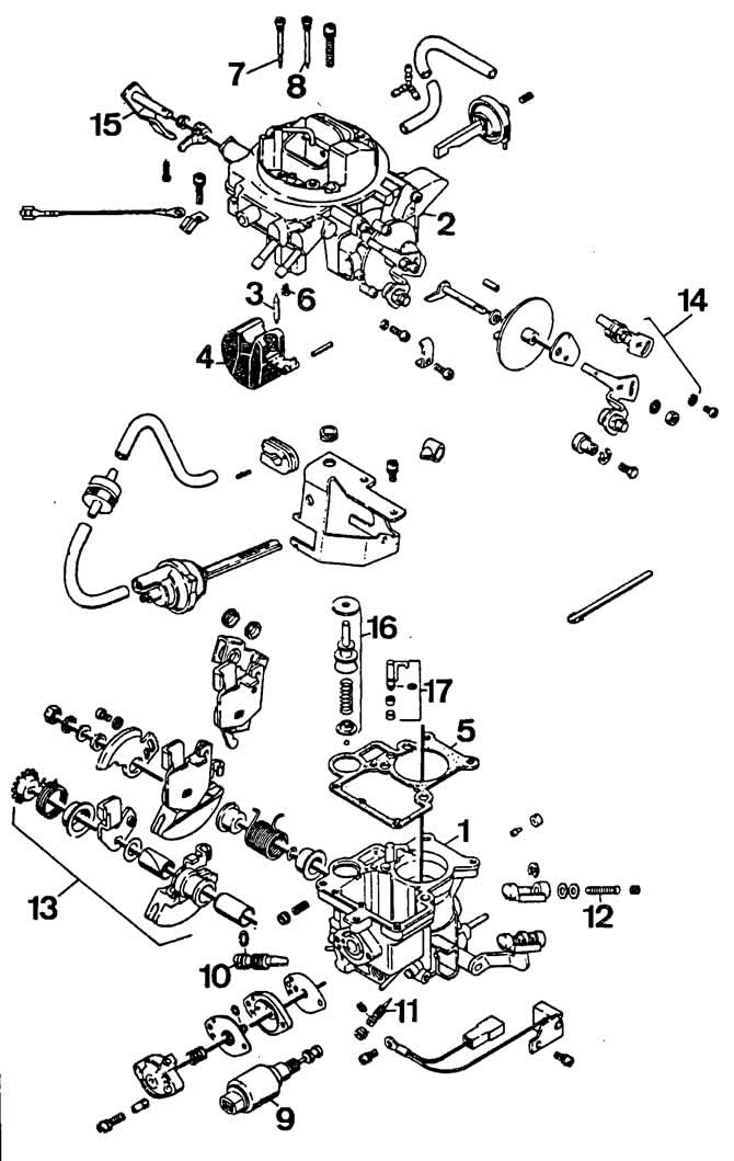
Pierburg 1B1 carburetor parts:
1 - carburetor body;
2 - carburetor cover;
3 - needle valve;
4 - float;
5 - float chamber gasket;
6 — fuel jet of the main metering system;
7 — idle fuel jet;
8 — fuel jet of economizer;
9 - electromagnetic shut-off valve;
10 — idle mixture quantity adjusting screw;
11 — screw for idle mixture quality (composition);
12 — throttle valve opening adjustment screw;
13 - Throttle control levers;
14 — air damper control levers;
15 — accelerator pump drive lever;
16 — accelerator pump piston;
17 - accelerator pump nozzle
Carburetor adjustment
Adjusting the fuel level in the float chamber
The original can be viewed on the portal vwmanual.ru
Remove the carburetor cover.
Install the carburetor cover at an angle of 45° and check the distance between the float and the plane of the float chamber, which should be 27 mm.
To adjust, bend the float lever slightly behind the support point of the needle valve. The float should rest on the valve needle at a right angle; in this case, the elastic pusher should not be recessed.
Adjusting the starting clearance of the air damper
Pull the choke control handle all the way out until the choke drive lever reaches the stop.
Connect the vacuum pump hose to the air damper pneumatic drive (see photo).
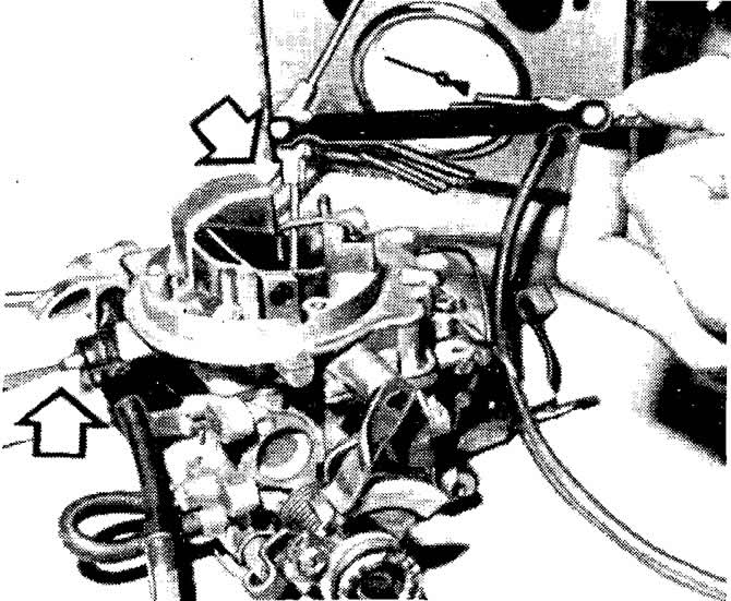
Adjusting the starting clearance of the air damper. The upper arrow shows the feeler gauge for measuring the starting clearance, the lower arrow shows the adjusting screw of the air damper pneumatic drive rod.
Create a vacuum of 500 mbar in the pneumatic drive and measure the starting gap of the air damper, which should be within 3.2±0.15 mm. If not, set the required gap by turning the adjusting screw of the pneumatic drive rod of the air damper.
After adjustment, make sure that the marks on the starter cover and the carburetor body are aligned.
Adjusting the throttle opening
This adjustment is made without removing the carburetor from the vehicle.
Fully push the air damper control handle in.
Connect the vacuum gauge hoses to the vacuum regulator of the ignition timing sensor-distributor and the carburetor.
Start the engine.
By screwing in the adjusting screw (see photo) for opening the throttle valve, increase the opening of the throttle valve until the increase in vacuum stops.
Turn the adjusting screw until a minimum vacuum is obtained, then turn it back another ¼ turn.
Install a new plug onto the throttle valve adjusting screw.
Adjust engine idle speed.
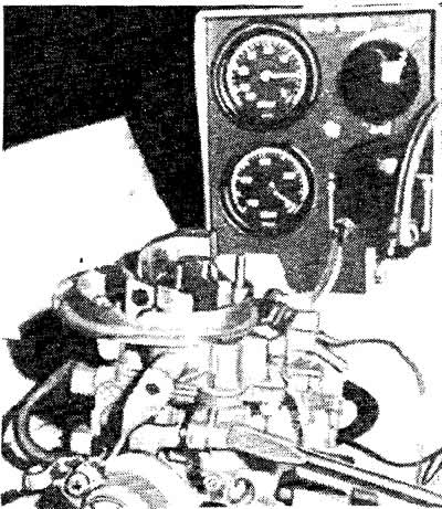
Adjusting the throttle opening
Adjusting the throttle opening
Pull the choke control handle out fully.
Make sure that the mark (see photo) on the throttle control sector is opposite the end of the throttle limit screw.
Check the starting clearance of the throttle valve, which should be within 0.8±0.05 mm. If not, set the proper clearance with the throttle valve limiting screw resting on the throttle control sector.
Install the carburetor in place and check the engine's fast idle mode at a coolant temperature of at least 60°C, which should be 4300-4700 rpm.
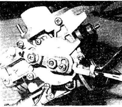
Adjusting the throttle valve starting clearance
Checking and adjusting the performance of the accelerator pump
Place a funnel with a measuring cup under the carburetor.
Fully push the air damper control handle in.
Slowly press the accelerator pedal ten times until it stops.
Measure the amount of fuel in the measuring cup: in ten cycles the accelerator pump should deliver 15±2 cm of fuel.
If necessary, adjust the performance of the accelerator pump by moving the cam of the pump drive lever on the bracket, after loosening the lock screw.
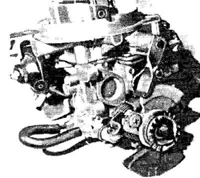
Adjusting the performance of the accelerator pump
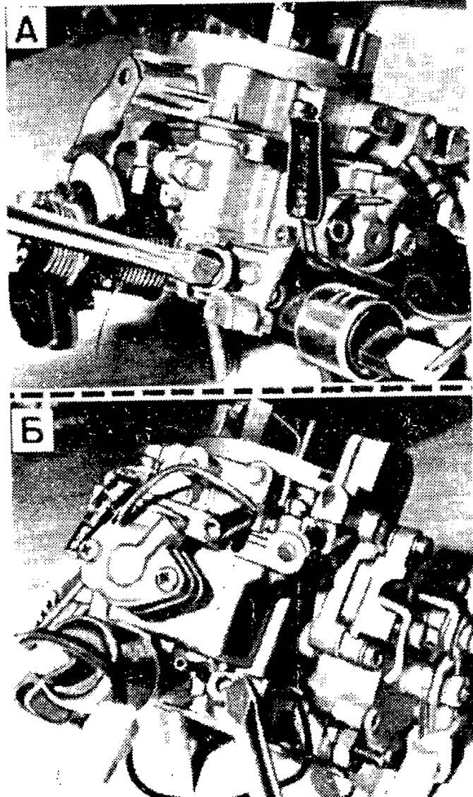
Idle speed adjustment screws:
A - mixture quantity screw;
B - screw of mixture quality (composition)
Adjusting engine idle speed
Idle speed adjustment must be performed on a warm engine with adjusted clearances in the valve drive mechanism and with the ignition timing set correctly.
Connect the tachometer and gas analyzer in accordance with the operating instructions.
Using the mixture quantity adjusting screw (see photo), set the crankshaft speed within 900-1000 rpm.
Using the mixture quality (composition) adjustment screw, achieve a carbon monoxide (CO) content in the exhaust gases within 0.5-1.5%.
If necessary, restore the crankshaft speed to 900-1000 rpm, then adjust the CO content again. Perform these operations until the idle speed and CO content simultaneously correspond to the data.
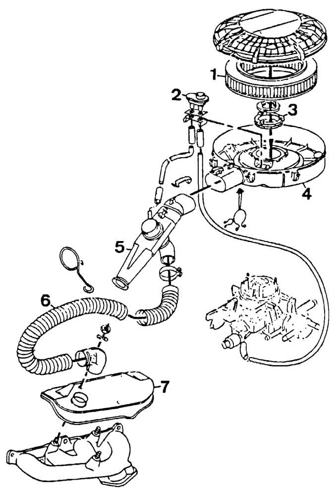
Air filter parts:
1 - filter element;
2 — carburetor body heating thermostat;
3 - seal;
4 — body;
5 — air intake pipe with thermostat;
6 — heated air intake hose;
7 — heated air intake shield
Visitor comments