
Vehicles with a 1.4 liter BCA petrol engine
Removing
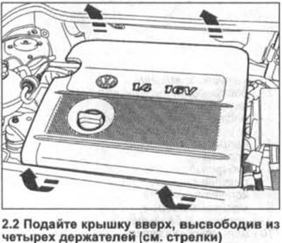
Attention! The upper engine protection cover consists of the upper and lower parts of the air filter.
1. Disconnect the top hose from the air filter.
2. Push the lid up, releasing it from the four holders (see arrows in illustration) and remove it from the throttle module.
Installation
3. Install the cover on the throttle module and on the four holders, press it down and lock it.
4. Connect the top hose to the air filter.
Vehicles with 1.4-/1.6-litre FSI petrol engine
Removing
Attention! The upper engine protection cover consists of the upper and lower parts of the air filter.
5. Release plug 1 of the intake air temperature sensor and disconnect it using a bent screwdriver, e.g. HAZET 818-1 or 818-2 (see illustration).
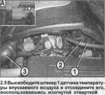
Insert a screwdriver into the slot behind the locking lug and move the locking lug towards the driver's seat (see part A in the illustration).
6. Disconnect the low pressure hose 2 by pressing on the bottom of the connector (see illustration 2.5).
7. Disconnect the air hose 3 by opening the retaining spring with suitable pliers, e.g. HAZET-798-9 (see illustration 2.5). Remove the hose from the cover.
8. Remove oil dipstick 1 (see illustration).
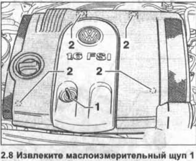
9. Push the engine cover up to remove it from the seats 2 (see illustration 2.8).
10. Remove the lid and place it upside down on a soft pad. Do not lose the rubber bushing of the oil dipstick.
11. Insert a dipstick into the guide tube to measure the oil level so that dirt does not enter this hole when working.
Installation
12. Remove the dipstick to measure the oil level from the guide tube.
13. Place the cover on the engine so that the mounting tabs are against their seats, and push the cover to lock into place.
14. Connect the plug and hose located under the cover.
15. Insert the oil level indicator into the guide.
Vehicles with 1.6 liter BGU/BSE/BSF engine
Removing
16. Remove the 1 engine oil level indicator from the guide (see illustration).
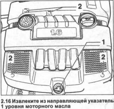
17. Release fasteners 2 of the cover and remove it by pushing up (see illustration 2.16).
The cover is installed in the reverse order of removal.
Vehicles with 2.0 liter FSI engine
Removing
18. Release the fasteners of the cover and remove it by pushing up (see arrows in illustration).
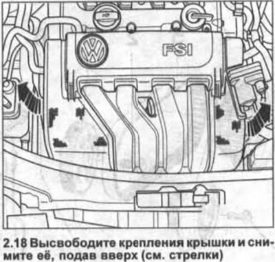
The cover is installed in the reverse order of removal.
Vehicles with 2.0 liter TFSI engine (GTI)
Removing
19. Squeeze the clamp 1 on the air hose nozzle with appropriate pliers, for example, VAS-5024A or HAZET-798-9 and slide it onto the hose (see illustration).
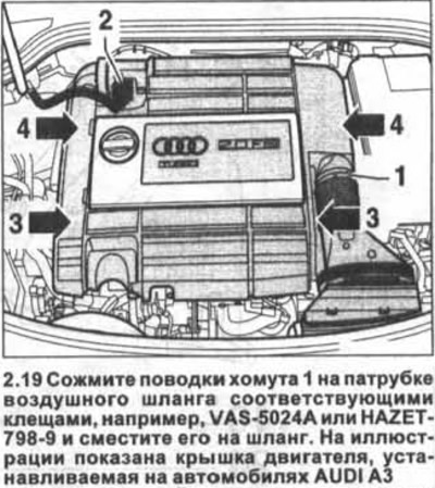
20. Move the rubber cuff to the turbocharger.
21. Disconnect plug 2 from the intake air mass flow meter and set it aside from the work area (see illustration 2.19).
22. Insert your hand from the side under the cover and release the engine cover from the front first (see arrows 3 in illustration 2.19), and then behind (see arrows 4).
The cover is installed in the reverse order of removal.
Diesel vehicles
Removing
23. Sharply push up the front of the cover (see arrows A), and then pull it forward when viewed in the direction of travel, and release the back of the cover from the fastening (see arrow B).
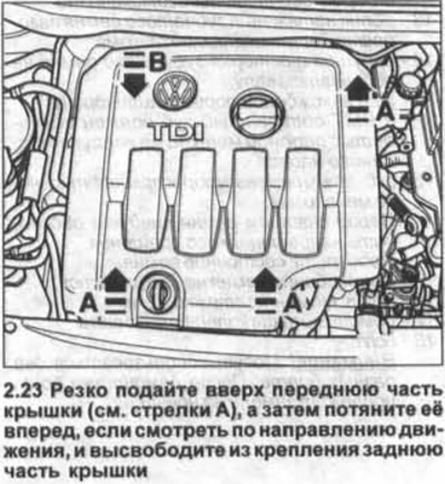
1.9-/2.0 liter diesel engines other than AZV/BKD engines
For vehicles with AZV / BKD engines, the cover is structurally slightly different, but its removal is identical (see illustration 2.23a).
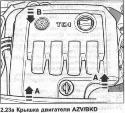
Installation
24. Fix the back of the cover, and then install it over the mounting points A and push it from above to fix it (see illustrations 2.23 and 2.23a).
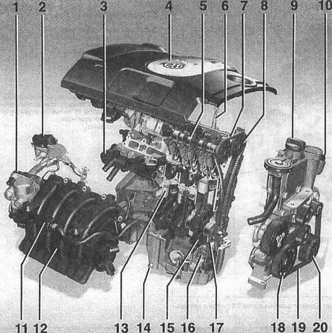
1.6 liter FSI engine (85 kW, 115 hp. With.):
1 - throttle module
2 - exhaust gas recirculation valve
3 - thermostat housing
4 - upper protective cover of the engine
5 - camshaft
6 - pin oil level indicator (probe)
7 - the purpose of the timing drive
8 - exhaust camshaft sprocket
9 - oil filler cap
10 - oil filter
11 - adsorber solenoid valve
12 - intake manifold
13 - piston
14 - engine oil drain plug
15 - crankshaft
16 - oil pump
17 - oil pump drive chain
18 - crankshaft belt pulley
19 - ribbed belt
20 - belt pulley of the air conditioning compressor
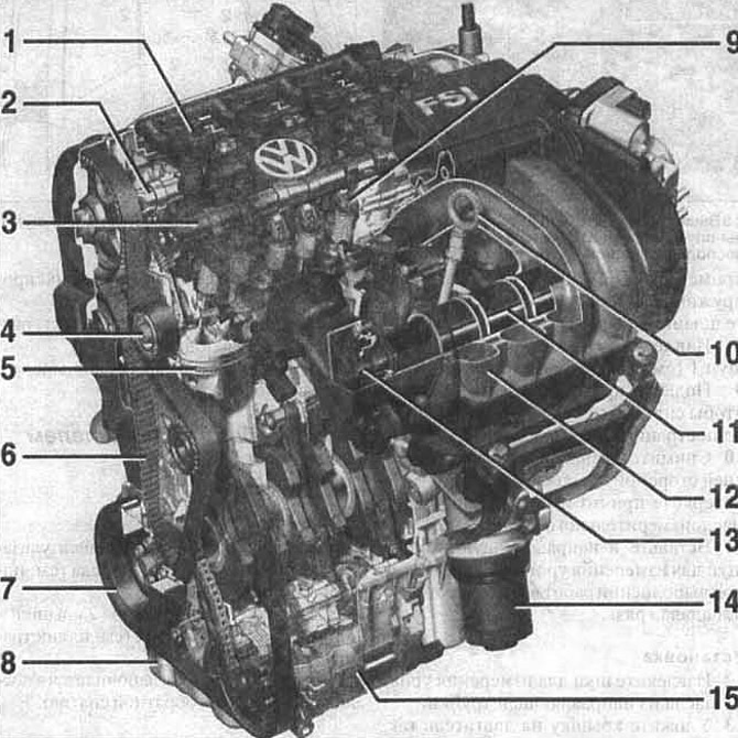
2.0 liter FSI petrol engine:
1 - ignition coil
2 - exhaust camshaft
3 - intake camshaft
4 - guide roller
5 - piston
6 - toothed belt
7 - belt pulley of the crankshaft
8 - oil pan
9 - roller balancer
10 - pin oil level indicator (probe)
11 - intake tract damper
12 - the upper part of the intake manifold
13 - intake duct damper drive shaft
14 - oil filter
15 - air conditioning compressor
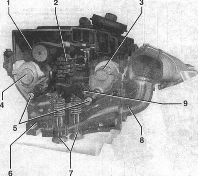
The gas distribution mechanism of a 2.0-liter diesel engine with four valves:
1 - roller balancer block «pump nozzle»
2 - block «pump nozzle».
Located in the center between the valves
3 - intake camshaft
4 - exhaust camshaft
5 - removable axle
6 - exhaust tract
7 - valves with a vertical arrangement.
When viewed from above, the valves are at an angle of 45°relative to the longitudinal axis of the engine
8 - intake tract
9 - rocker
Visitor comments