



Manual transmission
Press the accelerator pedal fully and lock it in this position (for example by laying a brick).
Check whether the lever on the high-pressure fuel pump has reached the limiter without any pressure being applied to it.
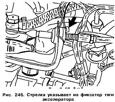
If necessary, remove the retainer (indicated by the arrow in Figure 246) and insert it into the other slot.
Check the traction adjustment again and adjust if necessary.
Automatic transmission
Before making any adjustments with the engine running, the gear selector lever must be set to the "P" position and the parking brake must be applied. The position of the accelerator rod must be adjusted if the engine was adjusted at idle.
The length of the rod must be adjusted so that the fuel injection pump lever rests against the adjusting screw 2 (figure 247) idle speed, and the gear selector is in the "N" position. Otherwise, upshifts will be delayed at medium speeds, and the gearbox will not be able to switch to "E" mode (Figure 247 shows the location of the fuel injection pump lever, and Figure 248 shows the location on the gearbox).
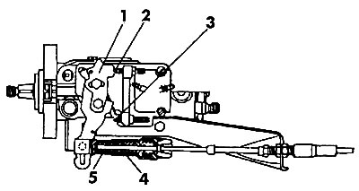
Figure 247. Fuel injection pump control components: 1 - fuel injection pump lever; 2 - idle speed adjusting screw; 3 - adjusting screw for maximum engine speed; 4 - spring of the device for switching on the maximum power mode; 5 - return spring |
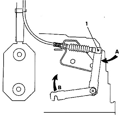
Figure 248. Automatic transmission control lever: 1 - in the idle position, the spherical joint bushing should fit freely against the joint head; A - until it stops during idle speed; B - until it stops when switching on the maximum power mode |
Move the gear selector lever to position "P". Remove the pump cover.
Check the idle speed and maximum speed and adjust if necessary. These values should be respectively the following: (850±100) rpm and (5350±50) rpm.
Loosen the nut that adjusts the accelerator rod and disconnect the end of the cable. Remove the retainer and remove the head from the fuel injection pump lever.
Move the spherical head from position "A" along the transverse groove of the fuel injection pump lever (idling) to position "B" (maximum rotation speed) by (32±1) mm (figure 249).
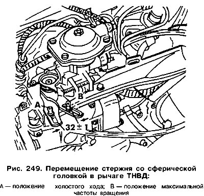
Replace the head and install the retainer.
Remove the rubber cap (arrow in figure 251) and loosen both nuts on the pump bracket.
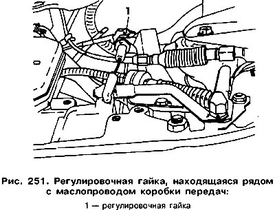
Set the gearbox lever to the "T" position and the casing bushing (shown by arrow) pull to the right (figure 250). The return spring should not be tensioned. In this position, tighten the adjusting nuts 1 and 2 on the bracket. Attach the accelerator rod. Press the accelerator pedal all the way down (maximum power mode). The second person should tighten the adjusting nut at this time (figure 251) next to the gearbox oil line until the gearbox lever hits the stop on the right side. Spring 4 (see figure 247) the device for switching on the maximum power mode must be compressed.
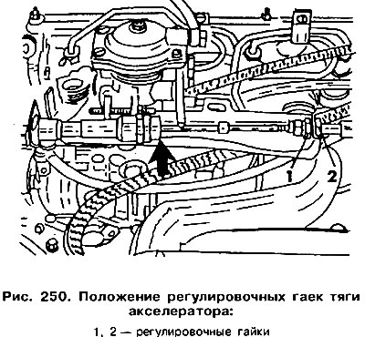
Tighten the accelerator rod nuts. The cable should not be taut.
To check if the installation is correct, do the following:
- check if the fuel injection pump lever touches the idle speed adjusting screw with the return spring fully depressed (see figure 247) and the gear selector in position "N";
- slowly press the accelerator pedal until the full power mode is reduced and check whether the lever on the injection pump touches the maximum speed adjusting screw. In this case, the spring of the device for engaging the full power mode should not be compressed;
- slowly press the accelerator pedal all the way down; the collector must rest against the limiter (buffer), and the spring of the full power mode switching device must be compressed.
Visitor comments