
Safety regulations when working with the power system
Caution: When carrying out installation work, especially in the engine compartment due to its dense layout, the following rules must be observed. Highways of all types (e.g. fuel, hydraulic, activated carbon absorber, cooling system, air conditioning circuit, brake system, vacuum), as well as electrical wires must be laid so. how they were originally laid out. To avoid damage to hoses, pipes or wires, sufficient space must be provided when working on all moving or hot parts. When removing and installing fuel gauge sender -G- or fuel pump (fuel delivery module) from filled or partially filled fuel tanks, the following must be observed. Remove the fuel pump fuse. The fuel in the power system is under pressure!
Removing
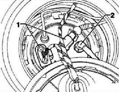
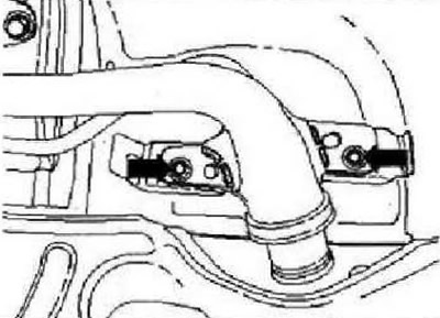
Strictly follow the safety regulations before starting installation work. With the ignition off, disconnect the battery ground wire. Loosen the filler cap screw and remove it. Drain the fuel from the tank and clean the area around the filler pipe. Remove the rear bench seat. Remove the cover from the fuel delivery module. Disconnect connector -1- and fuel line -2- from right (in the direction of travel) flange.
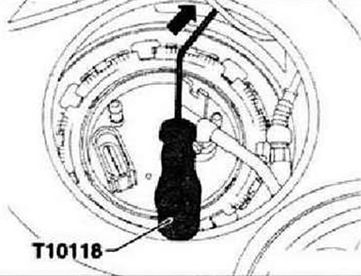
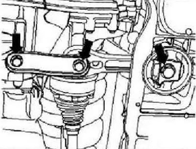
Release connector -arrow- on fuel pump control unit -J538- with tool -T10118- and unplug connector.
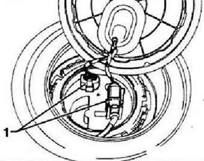
Disconnect connectors -1- from left (looking in the direction of travel) flange.
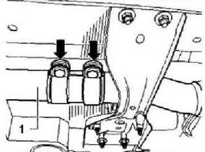
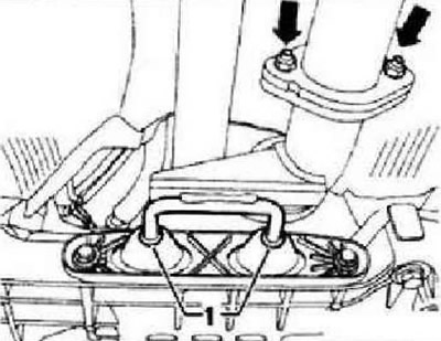
Unscrew the nuts of the double clamp -arrows- and slide it forward along the exhaust pipe.
Unscrew nuts -arrows- and pull exhaust pipe back. Remove rear exhaust system with middle and rear muffler.
All wheel drive vehicles
Unscrew pendulum support -arrows-. Remove cardan shaft.
Continuation for all cars
WARNING: The fuel in the pressure line is under pressure.
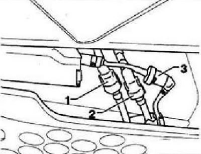
Disconnect fuel line -1- (black) and ventilation line -2- (white) at the junction. If auxiliary heater is installed, also remove fuel line -3-. -
Instructions: To unlock and remove the line, squeeze the retaining ring.
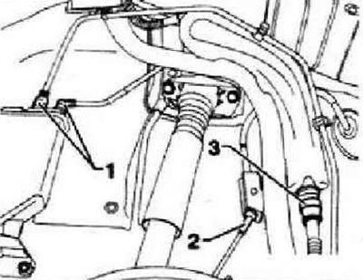
Unscrew the right rear wheel. Remove the rear right fender liner. Detach ventilation lines -1- from activated charcoal filter and filler neck -3-. Detach cable -2- from retainer. Remove the hatch and the filler cap of the fuel tank. Disconnect the ground wire at the filler neck.
Unbolt fuel filler neck from bodywork -arrows-.
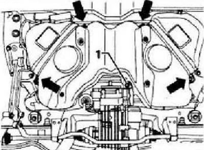
Unscrew securing bolt -1-. Unscrew band and securing bolts -arrows-. While doing this, support the fuel tank on the engine and gearbox jack -VAQ 1383 A-.
Installation
Using a second mechanic, guide the filler neck between the rear axle and the body. Then place fuel tank on jack -VAG 1383 A-. Raise fuel tank slowly to installation position and secure.
Instruction: Only bolts with washers turning on them may be used to fix the clamps of the fuel tank. When using other bolts, the clamps may warp when tightened.
Tighten new retaining bolts for tie-down straps -arrows- and new bolt -1- to 20 Nm + turn 90°further. Tighten securing bolts -arrows- for filler neck to 8 Nm + turn 90°further. Further installation is carried out, respectively, in the reverse order of removal. In doing so, the following must be taken into account. Ventilation and fuel lines should be laid without kinks. Check the fuel tank ground connection on the filler pipe. Make sure fuel hoses are properly secured. After installing the fuel tank, check whether the supply and ventilation lines are still attached to the fuel tank.
Visitor comments