
Instruction: If, during engine repair, large amounts of metal chips and wear products are found in the engine oil - the source of which is increased wear, for example, due to damage to the connecting rod bearing, then in order to avoid subsequent damage, in addition to thorough cleaning of the lubrication channels, replace the oil filter. Lubricate all support and work surfaces before assembly work. For assembly work, the engine must be mounted on the engine and gearbox bracket -VAS 6095-.
Belt drive
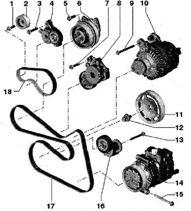
- 1 - 40 Nm and tighten by 90°. To loosen and tighten the mounting bolt, hold the compressor shaft with a 16 wrench, replace
- 2 - Compressor belt pulley
- 3 - 23 Nm
- 4 - Tensioner for compressor V-ribbed belt, loosen with a 16 wrench, secure with locking pin -T10060 A-
- 5 - 8 Nm
- 6 - Coolant pump with magnetic compressor clutch -N421-
- 7 - 23 Nm
- 8 - Loosen poly V-belt tensioner with 16 spanner -T10241- and secure with locking pin -T10060 A-. On vehicles with a manual gearbox, an overrunning roller is installed instead of a tensioner. Mounting bolt tightening torque: 40 Nm
- 9 - 23 Nm
- 10 - Generator
- 11 - Belt pulley of the crankshaft. Mating surfaces must be free of oil and grease
- 12 - Mounting bolt, replace. The clamping surface of the bolt must be free of oil and/or grease. Insert thread with oil, secure belt pulley with counterhold -3415-, turning can be done in several steps. The tightening angle can be measured using a conventional goniometer disc
- 13 - 40 Nm and tighten by 90°. Removal and installation with vehicle raised, replace
- 14 - Air conditioning compressor
- 15 - 25 Nm
- 16 - V-ribbed belt tensioner, loosen with a wrench, secure with a 4 mm socket wrench
- 17 - V-ribbed belt, mark direction of travel before removing. When installing the V-ribbed belt, pay attention to the direction of travel and the correct fit on the pulleys and tensioners
- 18 - Compressor V-ribbed belt, mark direction of travel before removing. When installing the V-ribbed belt, pay attention to the direction of travel and the correct fit on the pulleys and tensioners
Cylinder block
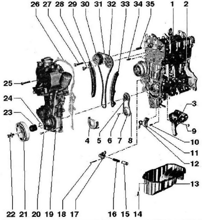
- 1 - Cylinder head with camshaft housing, the adjacent surface must not be processed. With integrated camshaft bearings. Remove the remnants of the old sealant, when installing, insert vertically from above with dowel pins into the holes of the cylinder head
- 2 - Cylinder block
- 3 - Bracket for accessories for tensioner and air conditioner compressor
- 4 - Overlay
- 5 - Asterisk for driving the oil pump and timing chain. Mating surfaces must be free of oil and grease
- 6 - 20 Nm and tighten by 90°, replace
- 7 - Asterisk. Secure the sprocket with support -T10172
- 8 - Drive chain, mark direction of travel before removing (installation position)
- 9 - 25 Nm
- 10 - 15 Nm
- 11 - Chain tensioner with strap for oil pump drive
- 12 - Pressure plate
- 13 - Oil pan, clean the seating surface before installing, apply silicone sealant -O 176 404 A2- when installing
- 14 - 15 Nm
- 15 - Piston for drive chain tensioner
- 16 - Pressure spring
- 17 - Chain tensioner
- 18 - 9 Nm
- 19 - Camshaft housing, when installing additionally use silicone sealant -D 176 501A1-. To facilitate installation, screw 2 locating pins M6x80 into the camshaft housing and cylinder block. To facilitate the insertion of the timing case, screw the oil pan with two bolts
- 20 - 10 Nm
- 21 - Belt pulley, follow the tightening method. The mating surfaces must be free of oil and grease. Secure belt pulley with counterhold -341522 - Retaining bolt, renew. The clamping surface of the bolt must be free of oil and/or grease, insert after oiling the threads. Secure the belt pulley against rotation with counterhold •3415-. The tightening angle can be measured using a conventional goniometer disc
- 23 - Support sleeve. Mating surfaces must be free of oil and grease
- 24 - O-ring, replace
- 25 - 50 Nm
- 26 - Gasket
- 27 - 40 Nm and tighten by 90°. Secure sprockets with counterholder -T10172-. Bolt with left-hand thread, replace
- 28 - 50 Nm and tighten by 90", replace
- 29 - Tensioner strap
- 30 - Valve timing regulator, do not disassemble
- 31 - Timing chain
- 32 - Sprocket for exhaust camshaft, secure sprockets with counterholder -T10172-
- 33 - Plank damper for the timing chain
- 34 - Guide pins, tightening torque: 20 Nm
- 35 - Support sleeve
Removal and installation of poly V-belt
Instructions: To remove the V-ribbed belt, loosen 2 tensioners.
Drain the coolant, to do this remove the hose -2-.
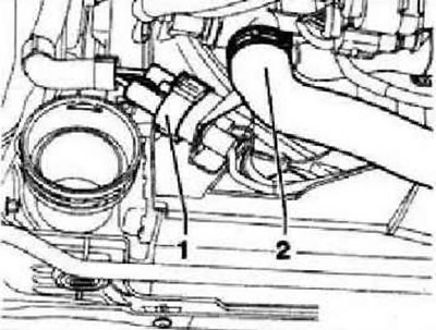
Position -1- should not be taken into account. Unlock the clip and remove the right-hand connector in the direction of travel from the radiator. Depending on the vehicle's equipment, remove the noise insulation or the underride guard. Mark the running direction of the V-ribbed belt. To loosen the V-ribbed belt, turn the tensioning element from above using a 16 mm wrench -T10241- in -direction of arrow-.
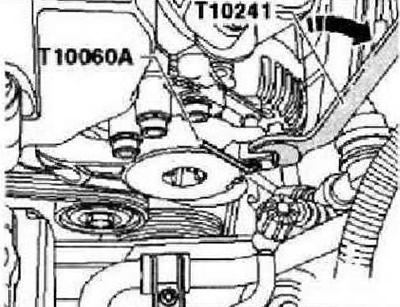
Secure tensioning element with locking pin -T10060 A-. To loosen the V-ribbed belt, turn the tensioning element from below using a 16 wrench in -direction of the arrow-,
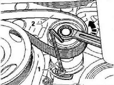
Secure the tensioning element with a 4 mm Allen key -1-. Remove poly V-belt -2-.
Visitor comments