



Caution: When performing installation work, especially in the engine compartment due to its dense layout, the following rules must be observed. Pipelines of all types (fuel, hydraulic, absorber, coolant, refrigerant, brake fluid, vacuum) and electrical wires must be laid as they were originally laid. To avoid damage to hoses, tubes or wires, it is necessary to provide sufficient space when working with all moving or heated components.
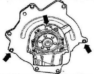
Check the clutch release bearing for wear and replace if necessary. Apply a thin layer of grease for gear engagement of clutch discs -G 000 100- to the release bearing, guide sleeve and splines of the input shaft. Check for the presence of centering bushings that determine the relative position of the engine and gearbox. If the bushings are missing, they must be installed in the cylinder block. Install the intermediate plate on the centering bushings of the engine flange "arrows".
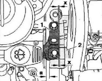
Align the engine mount as follows. There must be a distance "a" of at least 10 mm between the engine mount and the right side member. The cast edge in the engine mount "2" must be parallel to the bracket.
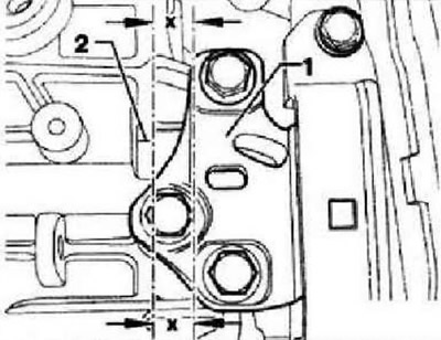
On the gearbox side, pay attention to the parallelism of the edges of bracket "1" and gearbox console "2".
Install the exhaust pipe.
All-wheel drive vehicles
Install the gearbox bracket for the angular gearbox.
The article is posted on this website www.VWmanual.ru
Instructions: First tighten the mounting nuts by hand.
Install the exhaust pipe support and tighten the mounting bolts "1" and "2" to a torque of 25 Nm.
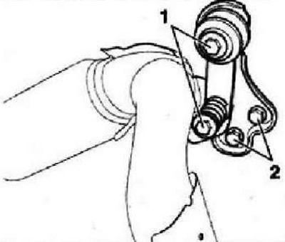
Install the subframe. Install the propeller shaft.
Continued for all cars
Install the joint shafts. Install the gearshift drive. Connect hose "1" of the hydraulic clutch slave cylinder. Install the pendulum support. Install the air conditioning compressor. Install the poly V-belt. Electrical connections and wiring. Fill with coolant. Install the air filter. Install the battery and battery mounting pad. Connect the battery. Press the engine casing at points "1" in the -direction of the arrow- downwards until it is secured at these points by latches. Connect the tester -VAS 5051B-. Delete the adaptation parameters from the memory and adapt the engine control unit to the throttle valve unit. Perform diagnostics of the vehicle systems. Complete diagnostics of the vehicle systems so that errors that may have been recorded during installation are automatically deleted from the fault memory.
Tightening torques
| M6 | 10 Nm |
| M8 | 20 Nm |
| M10 | 45 Nm |
| M12 | 60 Nm |
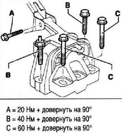
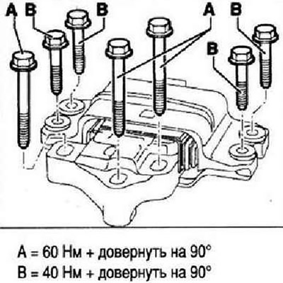
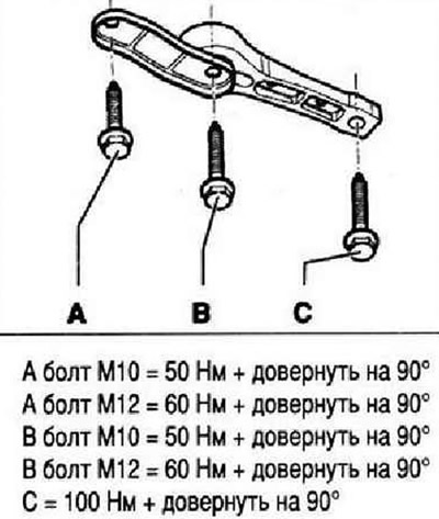
Powertrain support
Instructions: The component support mounting bolts are flexible bolts and must be replaced.
Engine support
Transmission support
Pendulum support
Visitor comments