
Fuel tank
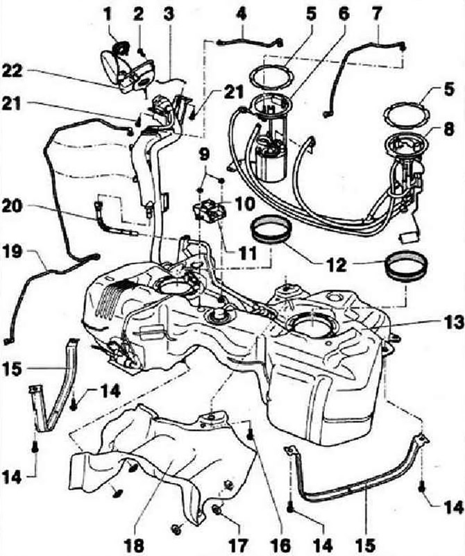
- 1 - Plug, replace if damaged
- 2 - Mounting bolt
- 3 - Earth connection, make sure the installation is secure
- 4 - Ventilation line to the absorber, make sure the installation is secure
- 5 - Retaining ring, 110 Nm, make sure that the installation is secure. Removing and installing with fuel gauge spanner -3087-
- 6 - Fuel supply module, install in the correct position on the tank. With fuel level sender -G-, if dirty, clean screen
- 7 - Supply line, black, fixed to the side of the fuel tank, make sure that it is installed securely
- 8 - Fuel level sender 2 -G169- with jet pump
- 9 - 3.5 Nm
- 10 - Bracket for fuel pump control unit -J538-
- 11 - Fuel pump control unit -J538-
- 12 - O-ring, replace. Install dry in the opening of the fuel tank, moisten with fuel when installing the flange
- 13 - Fuel tank
- 14 - 25 Nm, replace. To fix the clamps for fastening the fuel tank, it is allowed to use only bolts with washers turning on them. When using other bolts, the clamps may warp when tightened
- 15 - Clamp, observe installation position
- 16 - 20 Nm and tighten by 90°, replace
- 17 - Clamping washer
- 18 - Heat shield
- 19 - Ventilation line, fixed to the side of the fuel tank, make sure the installation is secure
- 20 - Ventilation line, make sure the installation is secure
- 21 - 8 Nm and tighten by 90°, replace
- 22 - Filler cap with rubber sheath
Mounting position of flange for fuel delivery unit and fuel level sender 2 -G169-
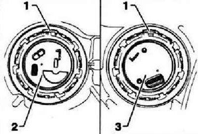
Fuel supply module -3-: tongue -1- points in direction of travel.
Fuel gauge sender 2 -G169- -2-: tongue -1- points in direction of travel.
Instructions: Ignore the arrows marked on the round nuts.
Visitor comments